Instruction Manual Supplement
D104328X012
DVC6200 Digital Valve Controller
February 2018
3
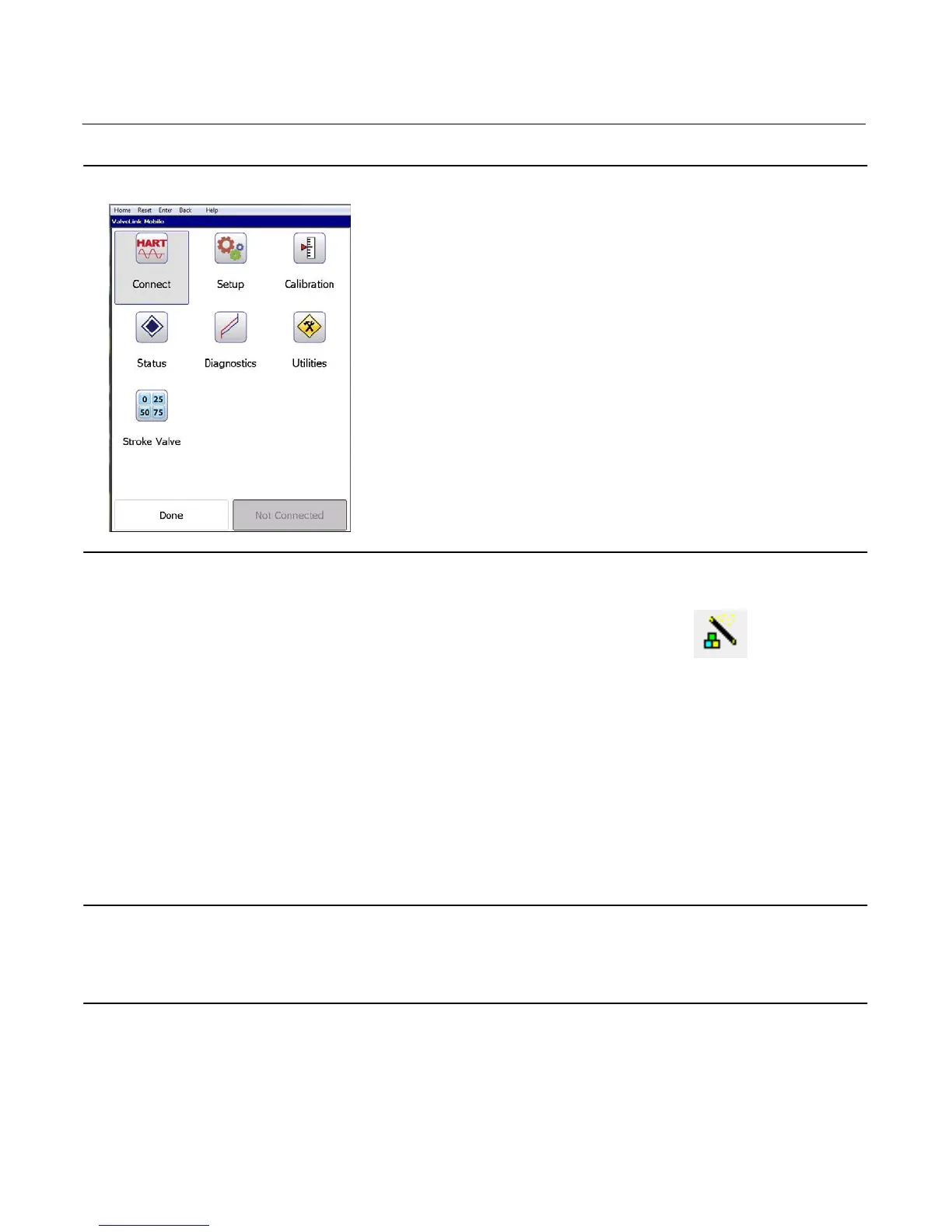
Figure 2. ValveLink Mobile Menu Screen
ValveLink software
1. Initiate the Setup Wizard either from the Instrument Setup menu or Setup Wizard Icon .
2. Select the appropriate Travel/Pressure Control Mode and the Relay Type.
3. Set the desired Pressure Units and the Max Supply Pressure for the application.
4. Select the required Actuator Information including: Actuator Make, Actuator Model, Actuator Size, and designate if
a Volume Booster or Quick Exhaust Valve is present.
5. Select Yes when prompted to Use Factory Default Settings.
6. When prompted to run an Auto Travel Calibration select No.
7. Place the instrument “In Service”.
Alignment Verification
Note
The rotary end mount array is the only array that must be verified. If the array is not at mid-travel, remove and reposition prior to
mounting the DVC6200.
All other arrays can be mounting in any direction, as they are not affected by north south polarity.
Alignment of the rotary array can impact the ability of the DVC6200 digital valve controller to properly follow the
setpoint. To ensure proper operation, the array must be mounted to the actuator with the label facing the gauge side
of the positioner when the valve is at 50% (mid) travel, see figure 3 below. If the array position is different, the array
should be removed and reoriented prior to mounting the DVC6200.

 Loading...


