EasyManua.ls Logo

Fisher TAC-M82 User Manual

Fisher TAC-M82
28 pages
To Next Page IconTo Next Page
Page #1 background imageLoading...
Page #1 background image
SERVICE
MANUAL
LW/MW/FM
STEREO
DOUBLE
CASSETTE
RECEIVER
7|
FISHER
C-M82
(
EUROPE/SPAIN
)
132
344
42
(Black)
132
344
47
(White)
SPECIFICATIONS
Amplifier
Section
Minimum
RMS
sine
wave
power
per
channel
at
6
ohms
within
rated
bandwidth
at
no
more
than
rated
THD
.............:cccsssssssecsessessereeees
35
Watts
Power
Bandwidth
........:cc:ccccssssceescsnsseccesennsstenss
60
Hz
20
kHz
Total
Harmonic
Distortion
..............sccssssssecescsseseesseenenens
0.9
%
FM
Tuner
Section
Usable
Sensitivity
(MONO)
............ccccccccceeseeeees
3.3nV/15.1
dBf
Signal-to-Noise
Ratio
(Mono)
65
dB
Stereo
Separation
at
1
KHZ
oo...
cccccceseeeeeeeeeeeeeeees
43
dB
MW
Tuner
Section
Usable:
Sensitivity,
assccicdisssesscsus
tasezsostessssaaesenecioeenesaaes
600yuV/m
Signal-to-Noise
Ratio
..............ccccssesscsseceececenecceeceescesseees
55
dB
LW
Tuner
Section
,
Usable:
SGnSitivity®
svssicccc.cccsius
ices
cance
sewsaven
ssewsertixcceosce
2300”uV/m
Signal-to-Noise
Ratio
..........ecccccssssssecseeesessenecensersecees
50
dB
Cassette
Section
Frequency
ReSponse
..............cssssccceesesssnreeneees
Wow
and
Flutter
(WRMS)
Channel
S@paration):
sieiceissicesiewesesies
ceseees
cccnedeseasadsssscaans
General
Power
RequireMents
...........ccccccsssscccesesssssssereseeneanee
AC
220V
(BO
AZ)
cscead
ees
iecesiuieescdasenesdivandanetnacaservdcesiescassenes
190
Watts
Dimensions
(WxHxD)
...
335
x
245
x
300
mm
WEIGHtE
(QPPTOX:)
a
sascesscscscnsndececsievevsesessccissevesddecavadrordeanaes
7.5
kg
Dolby
is
a
registered
trademark
of
Dolby
Laboratories
Licensing
Corporation.
Specifications
and
design
are
subject
to
change
without
notice.
REFERENCE
No.
WM-570026
Question and Answer IconNeed help?

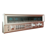
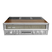
Do you have a question about the Fisher TAC-M82 and is the answer not in the manual?

Fisher TAC-M82 Specifications

General IconGeneral
BrandFisher
ModelTAC-M82
CategoryStereo Receiver
LanguageEnglish

Summary

Specifications

Amplifier Section

Key electrical parameters for the amplifier stage.

FM Tuner Section

Technical details for FM reception performance.

MW Tuner Section

Technical details for MW reception performance.

LW Tuner Section

Technical details for LW reception performance.

Cassette Section

Performance specifications for the cassette deck.

General

Overall unit specifications including power and dimensions.

Caution on RF Adjustment

FM Tuner Alignment

Procedures for aligning the FM tuner section.

FM Alignment

Specific steps for FM tuner alignment adjustments.

AM Tuner Alignment

Cabinet & Chassis Parts List / Exploded View

Package

List of packaging components for the unit.

Accessories

List of included accessories and their part numbers.

Cabinet

List of cabinet and chassis components.

Product Safety Notice

Cassette Deck Mechanism Parts List / Exploded View

Mechanism

Detailed list of cassette deck mechanism parts.

Double Cassette Deck Electrical Adjustment Procedures

Measuring Instruments Required

List of necessary tools for electrical adjustments.

Normal/Double Tape Speed Adjustment

Procedures for setting tape speed accuracy.

Head Azimuth Adjustment

Steps to align the tape head for optimal playback.

Playback Output Level Adjustment

How to adjust playback signal output levels.

Recording Bias Level Adjustment

Procedure for setting the recording bias level.

Recording Frequency Characteristic Response Adjustment

Steps to optimize recording frequency response.

P.C.Board Part List

IC Block Diagrams - Part 1

LA1266 Block Diagram

Block diagram for the LA1266 IC.

LA6462S Block Diagram

Block diagram for the LA6462S IC.

LA6458DS Block Diagram

Block diagram for the LA6458DS IC.

LA3400 Block Diagram

Block diagram for the LA3400 IC.

TC9171P Block Diagram

Block diagram for the TC9171P IC.

IC Block Diagrams - Part 2

LA3246 Block Diagram

Block diagram for the LA3246 IC.

CXA1101P Block Diagram

Block diagram for the CXA1101P IC.

STK4152MK2 Block Diagram

Block diagram for the STK4152MK2 IC.

LA5667 Block Diagram

Block diagram for the LA5667 IC.

LC4001B Block Diagram

Block diagram for the LC4001B IC.

LC4011B Block Diagram

Block diagram for the LC4011B IC.

LC4069UB Block Diagram

Block diagram for the LC4069UB IC.

IC Block Diagrams - Part 3

UPC1473HA Block Diagram

Block diagram for the UPC1473HA IC.

TC9148P Block Diagram

Block diagram for the TC9148P IC.

TC9150P Block Diagram

Block diagram for the TC9150P IC.

TC9152P Block Diagram

Block diagram for the TC9152P IC.

LC4913 Block Diagram

Block diagram for the LC4913 IC.

LB1641 Block Diagram

Block diagram for the LB1641 IC.

L78M05 Block Diagram

Block diagram for the L78M05 IC.

Point to Point Wiring Diagram

IC & Transistor Lead Identification

Related product manuals