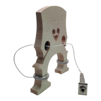
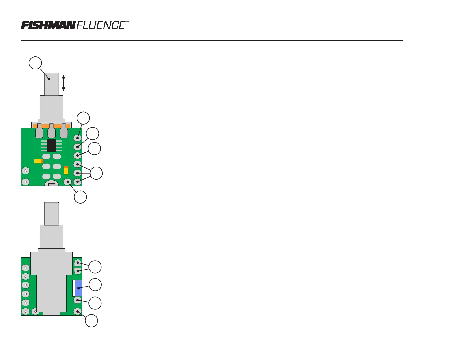
Phase Invert Control with Push-Pull Potentiometer - Connection Points, Controls, & Functions
1
2
10
9
8
7
6
5
4
3
Push-Pull Pot - Pull for Phase Invert
Volume/Tone IN
Volume/Tone OUT
Pickup Phase OUT
+9V-18V IN/OUT
Ground
Pickup Ground
Pickup Phase IN
Phase Invert Trim
Pot Function
Solder Pads
Note: All connections points (except the Pot Function Pads) are plated through-hole
style such that wires cab be inserted and soldered from either side.
1. Push-Pull Pot - The rotary function of the pot can be wired for several functions;
volume, standard tone control, and reactive tone control. (see diagrams for details)
Pulling up on the shaft engages the pickup phase invert feature. Pushing the shaft
down into the default position bypasses the phase invert.
2. Volume/Tone IN - Signal input for volume or reactive tone control. (Not used for
standard tone control.)
3. Volume/Tone OUT - Signal output for volume or reactive tone control. Main
connection for standard tone control.
4. Pickup Phase OUT - The pickup output from the phase select circuit.
5. +9V-18V IN/OUT - (+) DC Power / Battery input for inverter circuit. Two additional
connections are provided for convenient power distribution to active pickups.
6. Ground - Connection to main control cavity ground.
7. Pot Function Solder Pads - Solder pads for setting potentiometer control function.
Volume: Bridge pads with solder.
Standard Tone: Solder 0.15uF capacitor across pads. (see diagrams)
Reactive Tone: (Pads not used) Requires tone reactor accessory (see diagrams)
8. Phase Invert Trim - Fine gain adjustment for achieving preferred blend tone in
phase invert mode. Adjust to taste when using two pickups in combination. Range is -
2dB to +3dB.
9. Pickup Phase IN - Input for the pickup to phase selected.
10. Pickup Ground - Ground connection for the pickup input cable shield.