INSTALLATION
GASGUARD
The information contained within this guide is to cover typical installations,
however allowances must be made for the site-specific requirements. If in doubt
always contact Flamefast for further guidance.
TECHNICAL SPECIFICATION
Power Supply 100 – 240VAC 50/60Hz
Power Consumption 10W (Panel Only – inc. Aux Output)
Gas Solenoid Output Rating 5A @ 240V Max
Status Relay Rating 5A @ 240V Max
BACnet (COMING SOON) MS/TP over RS485
(Optional Extra) Baud: 9k6, 19k2, 38k4 or 76k8
127 Address (1/10th Load)
Operating Conditions Temp 0 - 50°C
Humidity 0 - 95% (NC)
IP Rating IP65 (Providing rear entry sealed)
Housing Material Flame Retardant ABS
Colour Light Grey (RAL7035)
Approval CE, UKCA
IMPORTANT
PLEASE READ CAREFULLY PRIOR TO INSTALLATION
1. This product must be installed by a competent/qualified person in accordance
with all relevant national and local regulations and legislations:
a. BS 6173:2020
b. IGEM/UP/2 Edition 3
c. IGEM/UP/11 Edition 3
d. IGEM/UP/19 Edition 2
2. If there is any question over the suitability for your application, please contact
Flamefast prior to installation.
3. This product must be mounted flush to the wall (or similar) using secure
fixings to prevent access to the rear.
4. This product must be connected to an accessible 5A fused spur and ensure
that the electrical rating of any components is not exceeded.
5. Ensure the mains supply is isolated and locked off prior to installation.
6. If this equipment is used in a manner not specified by the manufacturer,
protection provided may be impaired.
7. This product is designed for indoor use in ambient temperatures and standard
atmospheric conditions.
8. Following installation, the correct operation of the system and any associated
items should be verified.
9. All Gas Safety Systems should be safety checked by a competent/qualified
person at least annually.
PANEL LOCATION
The control panel should be mounted either next to the primary emergency exit
or next to the teachers bench (where applicable). Any additional emergency exit
should be fitted with a remote emergency stop button.
PANEL MOUNTING
The control panel should be mounted at a readily accessible height (typically 1.2
– 1.5m from the finished floor level) ensuring that the panel mounted Emergency
Stop Button is easily accessible. The panel should ideally be located next to the
exit with any additional exits covered by remote stop buttons.
For securing the panel to the wall there are four mounting holes, one in each
corner; these should be used to ensure that the IP rating of the unit is not
compromised.
With regards to cable entry, there is a 35mm cut out in the rear of the panel which
must be sealed if mounted externally. Cables can be brought in from the top or
bottom however allowances for internal components must be made, and mains
cables should not be run across the face of the PCB.
ALWAYS REMOVE THE PCB PRIOR TO DRILLING THE ENCLOSURE
ENSURE ANY GLANDS CLEAR COMPONENTS PRIOR TO DRILLING
ELECTRICAL CONNECTIONS
All electrical connections are to be made as indicated on the wiring diagram
(overleaf) and the maximum cable size should not be exceeded.
Any alarm (volt free) inputs must be wired using a dedicated volt free contact and
where more than one device is used these MUST be wired in SERIES.
It is recommended that ALL devices connected to the low voltage terminals be
done so using a screened cable as any voltage induction can cause fault conditions
or in more severe cases, cause damage to the panel.
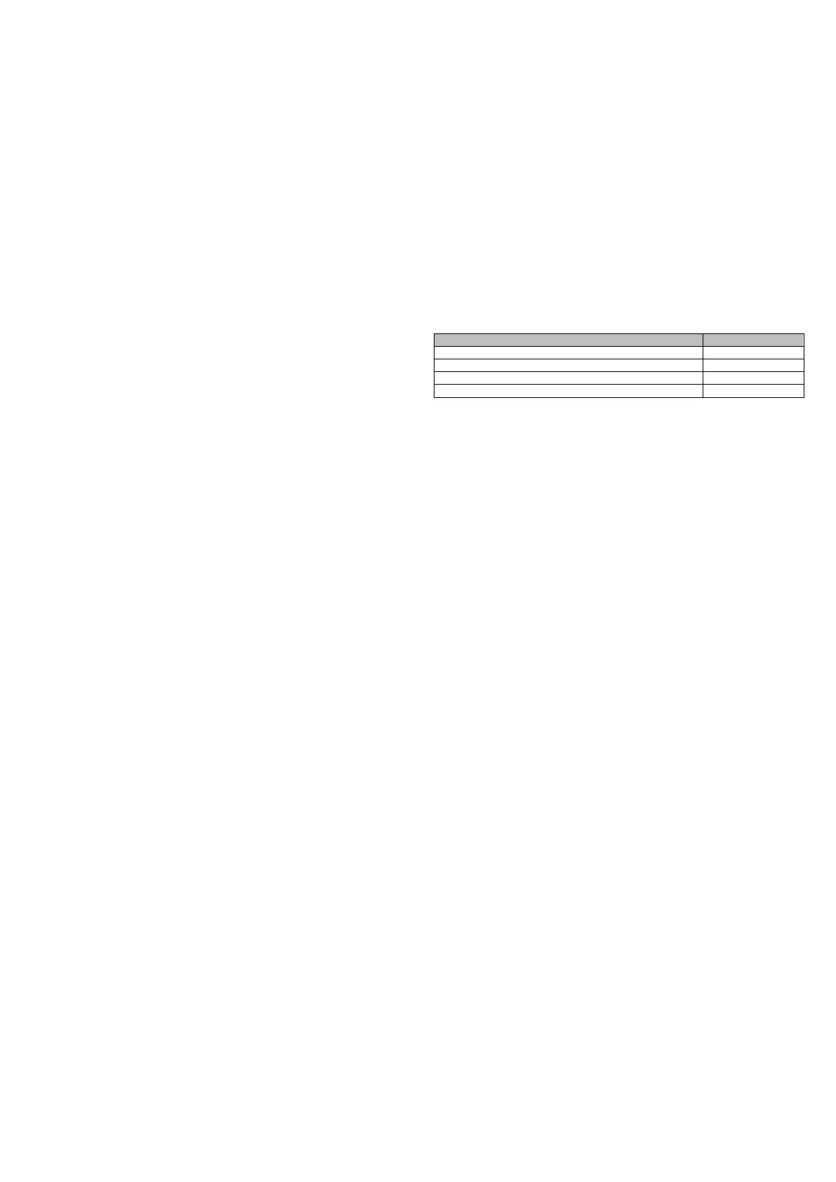
24V OUTPUT
The 24V DC auxiliary output is designed to power numerous Flamefast devices,
however the maximum rating of 300mA should not be exceeded. The device
consumptions are as below, however site-specific conditions and cable resistance
should also be considered:
Transmitter/BACnet Sensor (TR/BAC)
Fan Current Monitor (FCMON)
The output can be increased to 2,000mA with the use of the Flamefast Boxed
24VDC Power Supply (PS-24D).
BATTERY BACKUP (COMING SOON)
If the Flamefast battery backup is being used, this will maintain the integrity of all
monitoring circuits including the powering of all sensors. However, on loss of
power the Gas Valve Output and Status Relay will de-energise until power is
restored. The Gas Valve Output provides a switched live output, based on the
incoming supply, so this cannot be maintained on loss of power.
The battery backup provides 800mAh at 24V, and the backup time can be
calculated by dividing 800 by the load. The load is calculated based on the sum of
the consumption of any connected devices (as previously defined), plus an
additional 120mA for the panel operation.
An example when using two devices using 50mA, please see below:
800 / (120 + XX + XX) = X Hours
800 / (120 + 40 + 40) = 4 Hours
GAS AVAILABILITY TIMER
The Gas Availability Timer is used to ensure the system is isolated and the end of
each day. This can be set to 4, 8, 16 hours or disabled using a combination of DIP
switches 5 and 6 (default 16 hours).
No alarms will be raised, the system will simply fail to safe. This also ensures that
the gas pipework is tested daily.
GAS FILL & TEST TIME
DIP switch 1 can be used to increase the gas pipework pressurisation time from 5
to 10 seconds for larger volume systems. When the fill time is increased, this also
increases the test time from 30 to 60 seconds.
The fill and test time can be fully customised using the BACnet interface. Please
contact Flamefast for further details.
Although all Flamefast panels now use a Pressure Transmitter, they are backwards
compatible and can therefore be used with Gas Pressure Switches as used on all
panel pre-2017. When using a Pressure Switch, the test time will double to
compensate for the reduced sensitivity. The switch should be set to no less than
half of the incoming gas pressure.
 Loading...