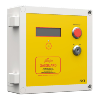
PRESSURE TRANSMITTER
The high accuracy Pressure Transmitter is used to monitor the gas pressure that
provides a 0-100 mBar output, scaled over 1-5VDC.
If the panel is displaying Transmitter Fault, this is caused by the panel not receiving
at least 0.5V from the transmitter. At 0kPa the transmitter gives an output of 1
VDC across terminals 2 and 3, so it can easily be verified is the transmitter is
functioning. If you are seeing less than 1V, ensure that the transmitter is receiving
24V both ends, and check the cabling.
If the transmitter does not respond to any pressure changes, this is more than
likely due to a blockage of the Vent Tube (see the Wiring Diagram) as this MUST
be left open to atmosphere. You must ensure that this is not folded or kinked, and
when cutting please ensure use a sharp blade.
Where the pressure transmitter does not see a pressure drop, please ensure that
it is installed into a downstream port (refer to the valve manufacturer
documentation for port configuration).
GAS SENSORS
Prior to connection of any gas sensors, please ensure that each core (24V, 0V, A
and B) is independent as any voltage induction to the communications terminals
can cause irreparable damage to the sensor.
Any damaged sensors or address conflicts may result in multiple sensors not
displaying on the system, including those that are otherwise functioning.
GAS SOLENOID OUTPUT
If the panel appears to be operating correctly however there is no output to the
Gas Valve, check that the PCB mounted radial fuse are still intact. These is located
just above the mains in terminals (please see wiring diagram for details).
LCD
If on power-up the LCD backlight illuminates however no text can be seen, the
text is too dark, or the text cells are completely dark the contrast may require
adjusting. This can be done by adjusting the potentiometer located to the bottom
right of the ribbon cable connector.
Is the LCD is simply displaying random characters there has been a breakdown in
communication between the Main PCB and the LCD. Removing power to the panel
then powering back up will re-establish the connection and the panel will return
to normal operation.
CO2 SENSORS
CO2 sensors should display circa 400ppm in outdoor air. However, they are
susceptible to contamination from fine dusts of cleaning solvents which can
distort the infra-red optics. ‘Poisoning’ of the sensor may cause it to display a high
reading.
In such instances, power cycle the sensor momentarily, then leave continuously
powered for 24 hours, after which the sensor will automatically recalibrate.
Sensor should see outside CO2 levels for at least 2 hours every 7 days.
MAINTENANCE
The system must be Serviced/Safety Checked at least annually by a FLAMEFAST
APPROVED ENGINEER and the panel has a built-in reminder. When the internal
timer reaches 30 days, ‘ANNUAL SERVICE DUE’ will display during operation – this
will not affect the functionality. If the system is controlling as Gas Solenoid Valve,
this must be by a Gas Safe Registered Engineer as check should be made to ensure
the valve closing and is not passing.
 Loading...