FLAMEFAST RESERVE THE RIGHT TO CHANGE PRODUCT SPECIFICATION WITHOUT PRIOR NOTICE GG_V3.00_OM_022024
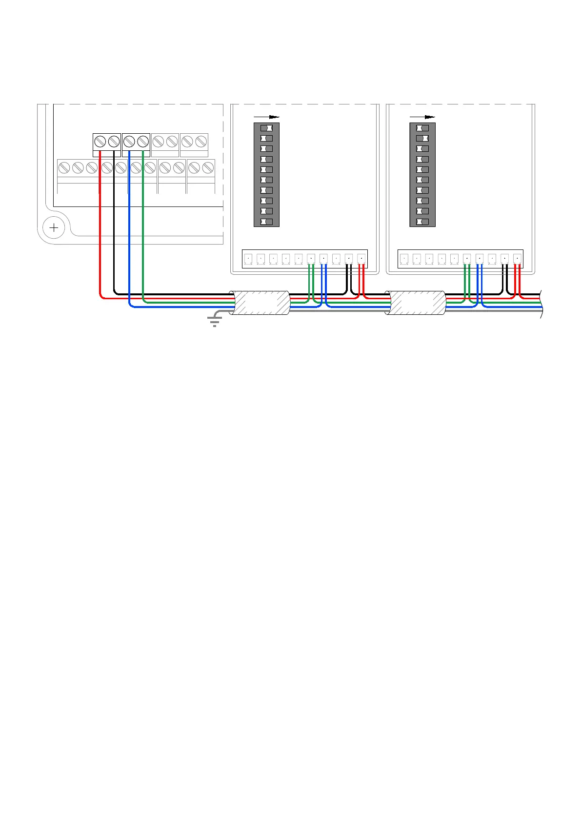
PLEASE SEE BELOW CONNECTIONS WHEN CONNECTING TO THE PANEL
SENSORS MUST BE WIRED IN ONE CONTINUOUS DAISY CHAIN. STAR WIRING CONFIGURATIONS MAY CAUSE THE PANEL TO ‘LOSE’ SENSORS
ALL SENSORS MUST BE SET TO DIFFERENT ADDRESSES, AND WE RECOMMEND NUMBERING STARTING AT 1, 2.. IN THE ORDER THEY ARE WIRED FROM THE PANEL
OPERATION & COMMISSIONING
GASGUARD
OPERATION
The basic operation of the system is advised by the LCD readout:
1. Turn the Key to ON to requested gas, which will initiate the pressure test.
a. The valve will open for 5 seconds to pressurise the pipework.
b. A pressure measurement will be taken.
c. The pressure will be monitored for a drop over 30 seconds.
d. If a pressure drop of more than 10% of the initial test pressure is
detected, the panel will alarm and advise.
e. If no pressure drop is detected, the panel will open the gas valve.
2. Turn the key to OFF to switch off the gas supply.
THE KEY SWITCH SHOULD BE TURNED TO THE OFF POSITION
AND THE KEY REMOVED WHEN THE ROOM IS UNOCCUPIED
COMMISSIONING
Once the installation is complete a functionality test must be carried out to verify
the correct installation & operation of the system – the gas must be live.
1. Turn the key switch to the ON position to ensure the gas valve output and
pressure transmitter are functioning correctly.
2. Press the panel mounted emergency stop button ensuring that all outputs are
isolated and the panel alarms accordingly.
3. Once all outputs have been proved, the gas proving function must be tested
by opening an outlet during the system test and ensure that the pressure drop
registers and the panel alarms accordingly.
4. The correct operation of any interfaced devices such as Remote Stop Buttons,
Intake/Extract Fans and Gas Sensors must also be verified.
PLEASE CONTACT FLAMEFAST FOR FURTHER DETAILS.
INTERNAL BUTTONS
ENGINEER button
The ENGINEER button on the main PCB can be used to aid with commissioning.
Providing the Remote Stop interface is not in alarm, holding this button then
turning the key switch will energise the Gas Valve and Status outputs to aid with
commissioning. This will timeout after 60 seconds unless switched off by the key
switch, after which the button will need to be released and held again for use.
Whilst the button is being held in, the unit counts to 60 and displays the gas
pressure.
LEARN Button
The LEARN button is for use when there are Gas Sensors connected to the unit.
Pressing this button will display the Channel, Gas Type, Reading and Days until
Calibration is required and Days until EOL. The unit will display 4 channels at a
time for 5 seconds each (20 seconds total display).
Following the connection/removal of any gas sensors, this button needs to be held
in for 30 seconds. At the end of the above mentioned 20 second status display,
the unit will countdown from 10 after which it will indicate how many sensors are
connected and store the data. This will then be used as a reference point to show
if any sensors go ‘missing’ at any point.
INTERROGATE Button
Holding the INTERROGATE button will display the status of ALL inputs along with
the gas pressure. This can be easily used to identify any faults. This will remain on
for 5 seconds following the release of the button, after which it will display the
number of days until a service is due.
24V
GAS
SENSOR
+ - A B
SCREENED
CABLE
SCR
C NC
RELAY
10V
0V 24V
AC/DC
B A
BACNET
RST
NO
SCR
C NC
RELAY
10V
0V 24V
AC/DC
B A
BACNET
RST
NO
ON
1
2
4
8
16
32
64
B1
B2
EOL
SCREENED
CABLE
ADDRESS GAS SENSORS
USING CHANNELS 1-16 ONLY
(SEE FGS/FGD MANUAL FOR
FURTHER DETAILS)
PANEL
FGS/FGD No.1 FGS/FGD No.2
12 13
14 15
ADDRESS GAS SENSORS
USING CHANNELS 1-16 ONLY
(SEE FGS/FGD MANUAL FOR
FURTHER DETAILS)
ON
1
2
4
8
16
32
64
B1
B2
EOL
 Loading...