The Flamefast GASGUARD is a comprehensive gas pressure proving and interlock system designed to enhance safety in environments where gas is used. Manufactured in the UK, this system is engineered to monitor gas pressure, detect potential leaks, and provide interlock capabilities with other safety devices, ensuring a secure operating environment.
Function Description
The primary function of the GASGUARD is to perform gas pressure proving, which involves testing the integrity of the gas pipework before allowing gas to flow. When the system is activated, it first pressurizes the gas pipework for a short period (typically 5-10 seconds, adjustable for larger systems). Following this, it monitors the pressure for a drop over a set duration (e.g., 30-60 seconds). If a significant pressure drop (e.g., more than 10%) is detected, indicating a leak or open end, the system will alarm and prevent the gas valve from opening, thereby isolating the gas supply. If no pressure drop is detected, the system "proves" the pipework is safe, and the gas valve will open, allowing gas to flow.
Beyond pressure proving, the GASGUARD acts as a central interlock system. It integrates with various external safety devices, including remote emergency stop buttons, ventilation systems (intake and extract fans), CO2 sensors, and other gas detectors. This integration ensures that the gas supply is immediately isolated if any of these interfaced devices detect a hazardous condition or are activated. For instance, if a remote emergency stop button is pressed, a fire alarm is triggered, or a gas sensor detects dangerous levels of gas or CO2, the GASGUARD will de-energize the gas valve, cutting off the gas supply.
The system also incorporates a Gas Availability Timer, which can be set to automatically shut off the gas supply after a specified number of hours (4, 8, 16 hours, or disabled). This feature ensures that the gas system is isolated at the end of each day or after a defined period of use, contributing to daily safety checks and pipework integrity testing.
Usage Features
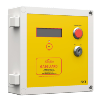
The GASGUARD is designed for user-friendly operation with clear visual feedback. The front panel features an emergency stop button for immediate gas isolation, a key switch for activating and deactivating the system, and a display that provides real-time information on system status, pressure readings, and any detected faults.
Activating the system involves turning the key switch to the "ON" position, which initiates the pressure test sequence. The display guides the user through the proving process, indicating when the valve is pressurizing, when the pressure is being monitored, and ultimately whether the system has "proved" safe or detected a fault. If a fault occurs, the display will provide specific error messages, such as "Transmitter Fault," "No Incoming Pressure," "XXmB Drop in XXXsec," or "Gas Sensor Error," helping users and engineers quickly identify the problem.
The system supports multiple remote emergency stop buttons, which can be wired in series, allowing for gas isolation from various points within a facility. It also integrates with ventilation interlocks, ensuring that gas can only be supplied when the ventilation system is operational, thereby preventing the buildup of hazardous fumes. CO2 interlocks further enhance safety by isolating gas if CO2 levels exceed safe limits, particularly relevant in environments with combustion processes.
For systems with multiple gas sensors, the GASGUARD manages and monitors these devices, displaying their status, gas type, readings, and calibration requirements. The "LEARN" button on the internal PCB allows the system to detect and store information about connected sensors, ensuring that any missing or malfunctioning sensors are identified.
Maintenance Features
The GASGUARD includes several features to facilitate maintenance and ensure long-term reliability. The system provides clear fault indications on its LCD display, making troubleshooting straightforward. Messages like "Calibration Due" or "New Sensor Required" alert users to upcoming or immediate maintenance needs for gas sensors.
An internal "ENGINEER" button on the main PCB assists with commissioning and testing. When held, this button can energize the gas valve and status outputs for a limited time (e.g., 60 seconds), allowing engineers to verify connections and functionality without fully proving the system. This feature is particularly useful during initial setup or routine checks. The "INTERROGATE" button allows engineers to quickly display the status of all inputs and the current gas pressure, aiding in fault diagnosis.
The system's design emphasizes robust construction with an IP65 rating (when rear entry is sealed), making it suitable for various indoor environments. The housing is made from flame retardant ABS, ensuring durability and safety.
Regular maintenance is crucial for the GASGUARD's continued effectiveness. The manual strongly recommends that the system be serviced and safety-checked at least annually by a Flamefast Approved Engineer. The panel includes a built-in reminder that displays "ANNUAL SERVICE DUE" when the internal timer reaches 30 days before the service is required. If the system controls a gas solenoid valve, it is imperative that a Gas Safe Registered Engineer performs checks to ensure the valve is closing correctly and not passing gas when it should be isolated.
The pressure transmitter, a key component for gas proving, can be easily verified for functionality by checking its voltage output. If the transmitter is not responding to pressure changes, it often indicates a blockage in the vent tube, which must be kept open to atmosphere and free from kinks or folds. The manual provides guidance on how to address common issues, such as adjusting LCD contrast or re-establishing communication between the main PCB and the LCD.
Overall, the Flamefast GASGUARD is a robust and intelligent gas safety system designed for reliable operation, ease of use, and comprehensive safety management in gas-equipped facilities.