7. Manual Switch (Optional)
For manual switch operation, use Flex-a-lite p/n 31148. Connect switch as shown on the wiring diagram
(previous page). To override engine temperature and turn fan on, connect the switch to the "M" terminal on
the control unit. NOTE: To prevent thermostatic activation (if only manual switch operation is desired),
omit the lead to the "+" terminal of the control box. "B", "G", "M+" and "M-" must remain connected. If
using a switch other than a Flex-a-lite manual switch, do not connect a ground wire to the switch!
8. Secure loose wires
Use the zip ties provided to secure the wires and prevent them from interfering with fan blades, belts, and
pulleys in the engine compartment. Reconnect the battery and insert the fuse into the fuse holder.
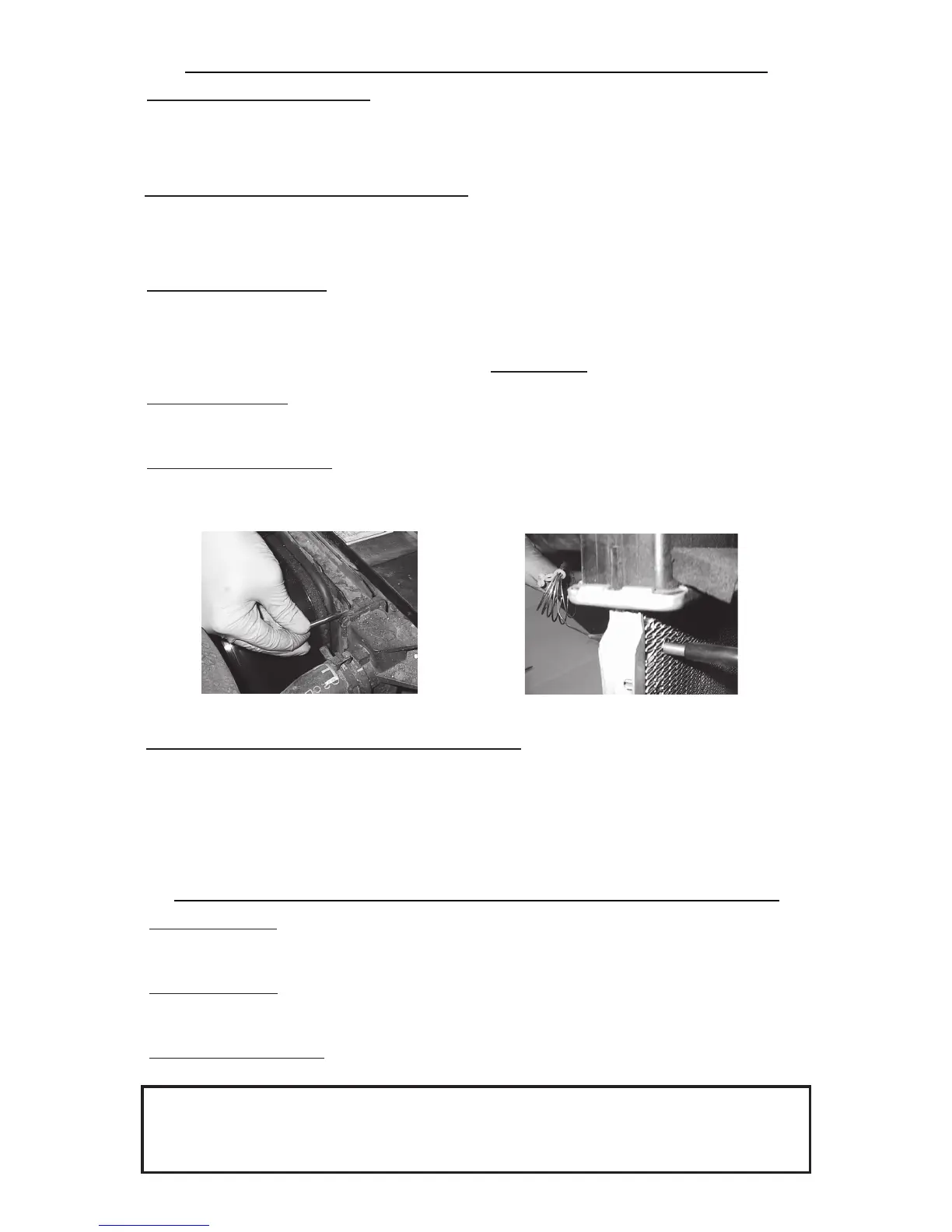
9. Insert temperature sensor
Locate the temperature sensor. Gently push probe through fins in radiator as close to the upper radiator hose
as possible. The rubber insulator cap should be used when possible to insulate any of the probe coming
through the front side of the radiator.
rev. 05-19-08 98111 Page 3 of 3
Wiring Instructions 111&133 Cont'd.
Install temp. probe near inlet hose...
then replace the insulator cap.
10. Adjust the temperature control knob on the control box
If you disconnected any hoses or drained coolant to install the fan, reconnect the hoses and refill the radiator.
Press the control knob (included in wiring kit) onto the control box shaft. Turn the knob clockwise until it stops.
Start the engine and allow it to idle. Using a hand-held thermometer (positioned near the inlet hose) or the
vehicle's temperature gauge, monitor the temperature. When the coolant temp. is slightly above normal or
desired temp. is reached, turn the knob counter-clockwise just until the fan turns on. From now on, the fan
should activate at this temperature setting. Adjust as necessary to maintain desired temperature.
Wiring Instructions - Model 123 & 143
1a.(Model 123 only): Wire the fan motors to power source (control unit or switch and relay if desired). Connect
the red wires from the fan motor to a 12v. positive (+) source. Connect the black motor wires to a ground (-)
source. NOTE: Failure to do this will result in incorrect operation and damage to the fan motors!
1b.(Model 143 only): Wire the fan motors to power source (control unit or switch and relay if desired). Connect
the black wires from the fan motor to a 12v. positive (+) source. Connect the red motor wires to a ground (-)
source. NOTE: Failure to do this will result in incorrect operation and damage to the fan motors!
2. Connect the fuse holder. Be sure to connect the provided fuse holder in-line with the positive (+) power
wire to protect the fan motors and your vehicle's electrical system from damage.
The Flex-a-lite Limited Warranty
Flex-a-lite Consolidated, 7213-45th St. Ct. E. Fife, WA 98424, Telephone No. 253-922-2700, warrants to the original purchasing user, that all Flex-a-lite products to be free of defects in material and
workmanship for a period of 365 days (1 year) from date of purchase. Flex-a-lite products failing within 365 days (1 year) from date of purchase may be returned to the factory through the point of
purchase, transportation charges prepaid. If, on inspection, cause of failure is determined to be defective material or workmanship and not by misuse, accidental or improper installation, Flex-a-lite
will replace the product free of charge, transportation prepaid. Flex-a-lite will not be liable for incidental, progressive or consequential damages. Some states do not allow the exclusion or
limitation of incidental or consequential damages, so the above limitation or exclusion may not apply to you. This warranty gives you specific legal rights and you may have other rights, which vary
from state to state.
The Flex-a-lite warranty is in compliance with the Magnuson-Moss Warranty Act of 1975.
6. Fan operation with air conditioning (if equipped)
Locate the wires coming from the A/C compressor. Determine which wire is ground and which is positive by
using a volt meter. Connect the positive wire to the supplied thin green wire by use of a piggyback connector.
Determine length needed to reach the control unit and trim to length. Attach a pink female connector to the end
of the wire and attach it to the "C" terminal on the control unit.
5. Ignition controlled power source
Locate fuse box. Find a circuit that is "hot " when the key is in the "ON" position. NOTE: DO NOT use the
DRL or brake/taillight fuse! Attach the included fuse tap to fuse. Attach a female connector to the thin red
wire included and connect to the fuse tap. Trim the wire so that it will reach the control unit. Attach a pink
female connector to end of wire and connect to the "+" terminal on the control unit.
 Loading...