Do you have a question about the Flex-a-Lite 294 and is the answer not in the manual?
Remove plastic radiator cover and the top half of the fan shroud.
Remove the fan and clutch assembly, noting pulley mounting.
Remove the lower shroud from the radiator assembly.
Locate potential mounting points for the fan assembly around the radiator.
Avoid mounting brackets directly to the radiator core; use cross braces or trays.
Attach the Variable Speed Controller to the shroud and drill holes for wire passage.
Connect motor wires and route control unit wires through drilled holes.
Connect the thick red and black wires from the kit to the VSC.
Connect circuit breaker to VSC and battery positive terminal.
Connect to ignition hot circuit and A/C clutch signal wire.
Install temperature probe into radiator fins and connect to VSC.
Turn ignition on, verify 12V at terminal #9, and check LED #4.
Run engine, engage A/C, and check if fans cycle with the clutch.
Adjust VSC screw to set fan turn-on and shut-off temperatures.
Understand how fan speed increases with rising temperatures.
Connect blue wire to 12V positive and black wire to ground.
Install an inline fuse holder with the positive power wire.
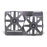
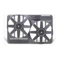
| Brand | Flex-a-Lite |
|---|---|
| Model | 294 |
| Category | Fan |
| Language | English |