Do you have a question about the Flex-a-Lite 264 and is the answer not in the manual?
Steps for safely removing the original fan and shroud assembly from the engine.
Initial safety steps including cooling the engine and disconnecting power sources.
Detaching the shroud from the radiator and disconnecting electrical components.
Detaching the fan clutch and lifting out the original shroud assembly.
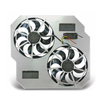
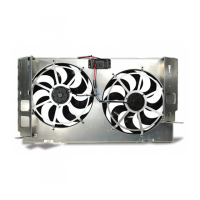
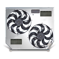
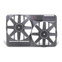
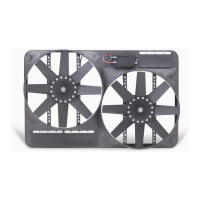
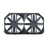
Attaching the new fan and shroud assembly to the radiator core.
Installing the passenger and driver side mounting brackets to the new shroud.
Specific installation steps for 2003 models, including overflow tank bracket.
Securing the new shroud, reattaching related components, and installing the temperature sensor.
Wiring the fan motor control unit to the vehicle's electrical system.
Connecting the main power wires and installing the circuit breaker.
Tapping into ignition, A/C trigger, and temperature sensor wires.
Connecting an optional manual switch for fan control override.
Initial checks, engaging A/C, and verifying fan operation.
Turning on the ignition and checking the status of indicator LEDs.
Engaging the A/C system to test fan response and indicator lights.
Adjusting the temperature sensor screw for desired fan cycling.
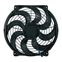
| Diameter | 16 inches |
|---|---|
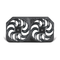
| Blade Material | Plastic |
| Engine Cooling | Yes |
| Material | Plastic |
| Type | Electric |
| Mounting Type | Radiator |
| Mounting Style | Pull |