Detail #1
Right Side Bracket
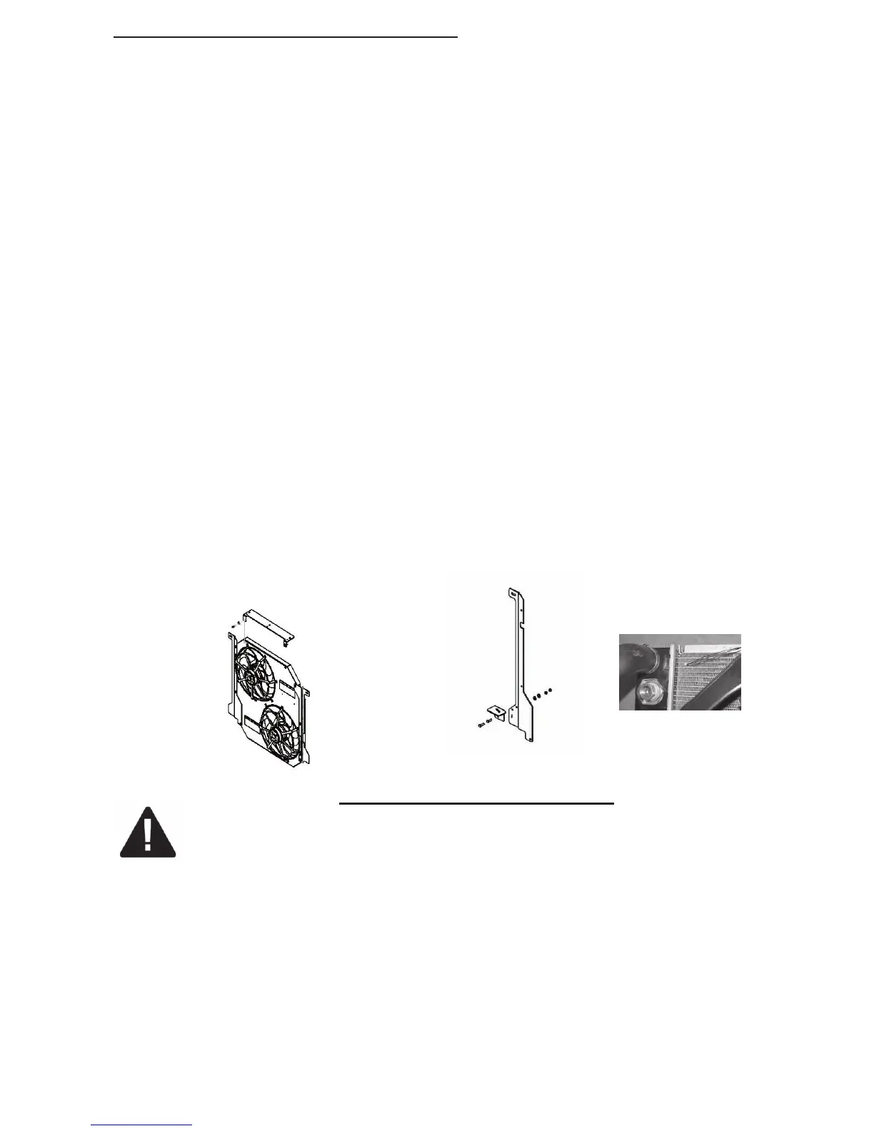
Detail #2
Left Side Brack-
Detail #3
Top Bracket
#98264 page 2 of 4 Rev. 11-16-11
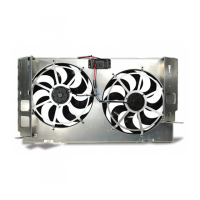
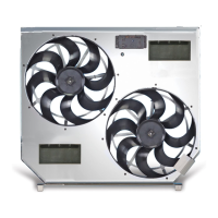
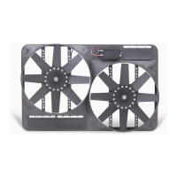
INSTALLATION OF ELECTRIC FAN & SHROUD:
1. Start by attaching passenger side bracket to the shroud with 10mm hex bolts and lock nuts (3ea).
see detail #1
2. Gently lower the fan/shroud into the vehicle placing the lower tab of the mounted bracket into the side
tank slot on passenger side. Slot is at bottom of radiator molded onto side tank. Examine old shroud tabs
for reference.
3. While holding up driver’s side, insert factory 13mm bolt with black spacer from kit #26419 securing top
of bracket to side tank mount on passenger’s side. CAUTION: Do not over tighten and be sure the bolt end
does not apply any contact to the radiator tank.
4. Move air box on passenger’s side forward and reattach using factory 10mm nut.
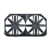
5. Attach driver’s side bracket to shroud with shroud in place using 10mm hex bolts and lock nuts (3ea).
see detail #2
*For model year 2003, use steps 6a and 6b; for all others, go to step #7.
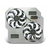
6a. For model year 2003 only: Attach over flow mount bracket with bolts in kit bag #26419. see detail 4
NOTE: Place the lower tab of the mounting bracket into the side tank slot on driver’s side before bolting to
shroud.
6b. For model year 2003 only: Locate 2 black spacers found in kit bag #26419 prior to installing bracket
to shroud. Use these as needed with the upper factory (drivers side bolt) while mounting over flow tank and
fan back into place. CAUTION!
Do not overtighten and be sure the bolt end does not apply any contact to the radiator tank.
NOTE: Place the lower tab of the mounting bracket into the side tank slot on driver’s side before bolting to
shroud.
7. Remove “loom clips” from top of old factory plastic shroud by pinching expanded wings on under side
with needle nose pliers (these hold positive cable to secondary battery);
8. Insert “loom clips” into top replacement bracket.
9. Attach “loom clip” bracket to top of new shroud by aligning bolt thru holes of bracket to threaded
inserts on top inside face of shroud. see detail #3
10. Reattach windshield washer tube and battery cable into “loom clips” along new top mounted bracket.
see detail #1
11. Reattach overflow tube if removed earlier.
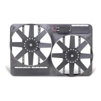
12. Locate the temperature sensor in the kit bag. Insert the temperature sensor into the radiator fins near
the inlet. Leave ¼” or less protruding from the surface of the radiator for optimum performance. The
wires will run out through the top corner of the fan shroud. These will be used later when wiring the Fan
Motor Control. see detail #5
WIRING THE FAN MOTOR CONTROL
FOLLOW THESE INSTRUCTIONS CAREFULLY TO AVOID DAMAGING THE CONTROL
UNIT, FAN MOTORS, AND YOUR VEHICLE! WHEN CRIMPING WIRES, ALWAYS USE A
QUALITY CRIMPING TOOL (DO NOT USE PLIERS OR OTHER DEVICES).
1. Find the thick red and black wire bundles in the wiring kit. Use the yellow butt connectors to crimp the red
wire to the short red wire on the Fan Motor Control, and the black wire to the short black wire on the Fan
Motor Control (see wiring diagrams on next page).
2. Determine the length needed to connect the red and black power leads to the battery terminals on the
primary battery on the drivers side and trim appropriately. Crimp a large yellow ring connector to the end of
the black wire and connect to the negative (-) battery terminal but DO NOT connect the red wire yet.
3. Find a convenient place to mount the circuit breaker between the Fan Motor Control and the positive (+)
battery terminal and use the 2 screws provided to mount it securely. Cut the red wire at the point where
you mounted the circuit breaker. Find the red boot for the circuit breaker and lay it on the breaker. Crimp
a small yellow ring connector to the ends of the wires and connect them to the circuit breaker. NOTE: BE
SURE TO CONNECT THE END COMING FROM THE BATTERY POSITIVE (+) TERMINAL TO THE
“BAT” TERMINAL ON THE CIRCUIT BREAKER (COPPER COLORED). Once both positive (+) wires are
connected to the circuit breaker, fold the top of the boot over and press to fit. This will help insulate the circuit
breaker from arcing.
Detail #4
Detail #5
 Loading...