L 26-6 230
20
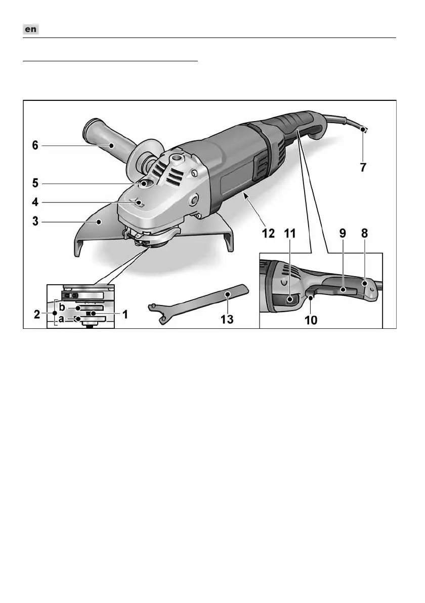
Overview
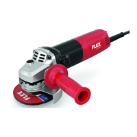
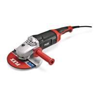
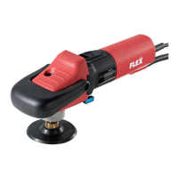
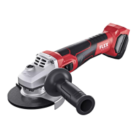
Different electric power tools are described in these instructions.
The illustrated electric power tool may differ in detail from the one which you purchased.
1 Spindle
2 Threaded flange
a Clamping nut
b Clamping flange
3 Quick-release guard
4 Gear head
With air outlet and direction-of-rotation
arrow.
5 Spindle lock
Secures the spindle when the tool
is changed.
6 SoftVib handle
Side handle can be fitted on the left, the
top or the right.
7 4.0 m power cord with plug
8 Switch handle
9Switch
Switches the power tool on and off.
10 Starting lockout/Locking button
Prevents the power tool from starting
up unintentionally and locks the
switch (9) during continuous operation.
11 Release button
For rotating the switch handle (8)
through 90°.
12 Rating plate (not illustrated)
13 Face spanner
 Loading...