INSTRUCTION HANDBOOK
PD22I / PD22P
PD22IP IH EN 74-125-102 v1.04
10 Interface and change of voltage
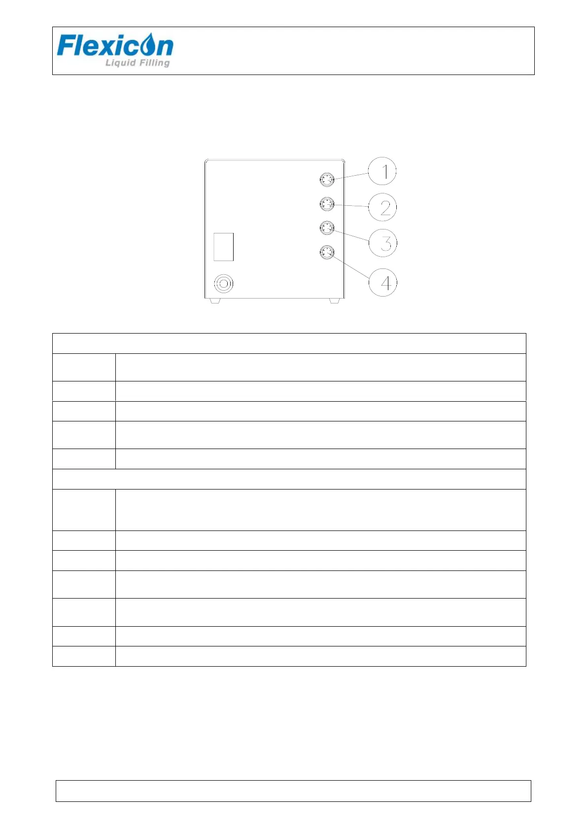
10.1 PD22 I Interface
INPUT FOR START SIGNAL
+5 - 50 VDC, min. 100 msec. positive-edge-trigged.
OUTPUT, +24 VDC, MAX. 500 MA.
STATUS OUTPUT, MAX. +24 VDC, 100 mA.
Pin 4 is grounded via an open collector during filling.
STATUS OUTPUT, MAX. +24VDC, 100 mA Pin 5 is complementary to pin 4.
INPUT FOR DISABLING.
+5 - 50 VDC. if this pin is activated, the drive will be disabled (no
dispensing).
OUTPUT, +24 VDC, MAX. 500 MA.
STATUS OUTPUT, MAX. +24 VDC, 100 MA.
Pin 4 is grounded via an open collector during filling.
STATUS OUTPUT, MAX. + 24 VDC, 100 MA.
Pin 5 is complementary to pin 4.
This socket is reserved for (RS-485) network communication.
This socket is reserved for (RS-485) network communication.