13
FI2
M1
M2
EB1
F10
F20
M4
HR-R
FI1
B1
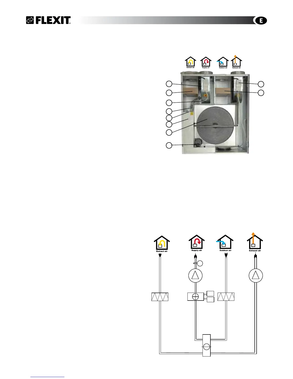
8 General Pictures/System Drawings
8.1 S3 R
General Picture - Rotor Heat Exchanger
1 (FI2) Extract air filter F 7
2 (FI1) Supply air filter F 7
3 (EB1) Heating battery, electrical
4 (F10-20) Overheating thermostat (manual reset)
5 (M1) Supply air fan
6 (M2) Extract air fan
7 (HR-R) Rotor heat exchanger
8 (M4) Rotor motor
9 Control box
10 Adjustment switch
System Drawing - Electrical Battery
B1 Temperature sensor, supply air
EB1 Heating battery, electrical
F10 Overheating thermostat (manual reset)
F20 Overheating thermostat (automatic reset)
FI1 Supply air filter
FI2 Extract air filter
M1 Supply air fan
M2 Extract air fan
HR-R Rotor heat exchanger
M4 Rotor motor
Extract air Supply Outdoor Exhaust
S3 R/S3 RK
Right model
(left model inverted)
Extract air Supply air Outdoor air Exhaust
6
2
5
1
3
4
9
10
8
7
gpd.sunwayinfo.com.cngpd.sunwayinfo.com.cn