© 2013 Flex Radio Systems. All rights reserved.
Installing the ATU inside the FLEX-5000
a. [Step only needed for older FLEX-5000s that do not have the threaded posts already installed] Remove the
four (4) nuts that are holding down the PA board, but leave the flat washers in place.
Do not discard the hex nuts.
b. [Step only needed for older FLEX-5000s that do not have the threaded posts already installed] Install a 3/4”
(1.9 cm) spacer on each threaded stud in place of the four (4) hex nuts that were just removed. Take care not to
over-tighten the spacers, so that you do not strip the threads. (See Figure 5)
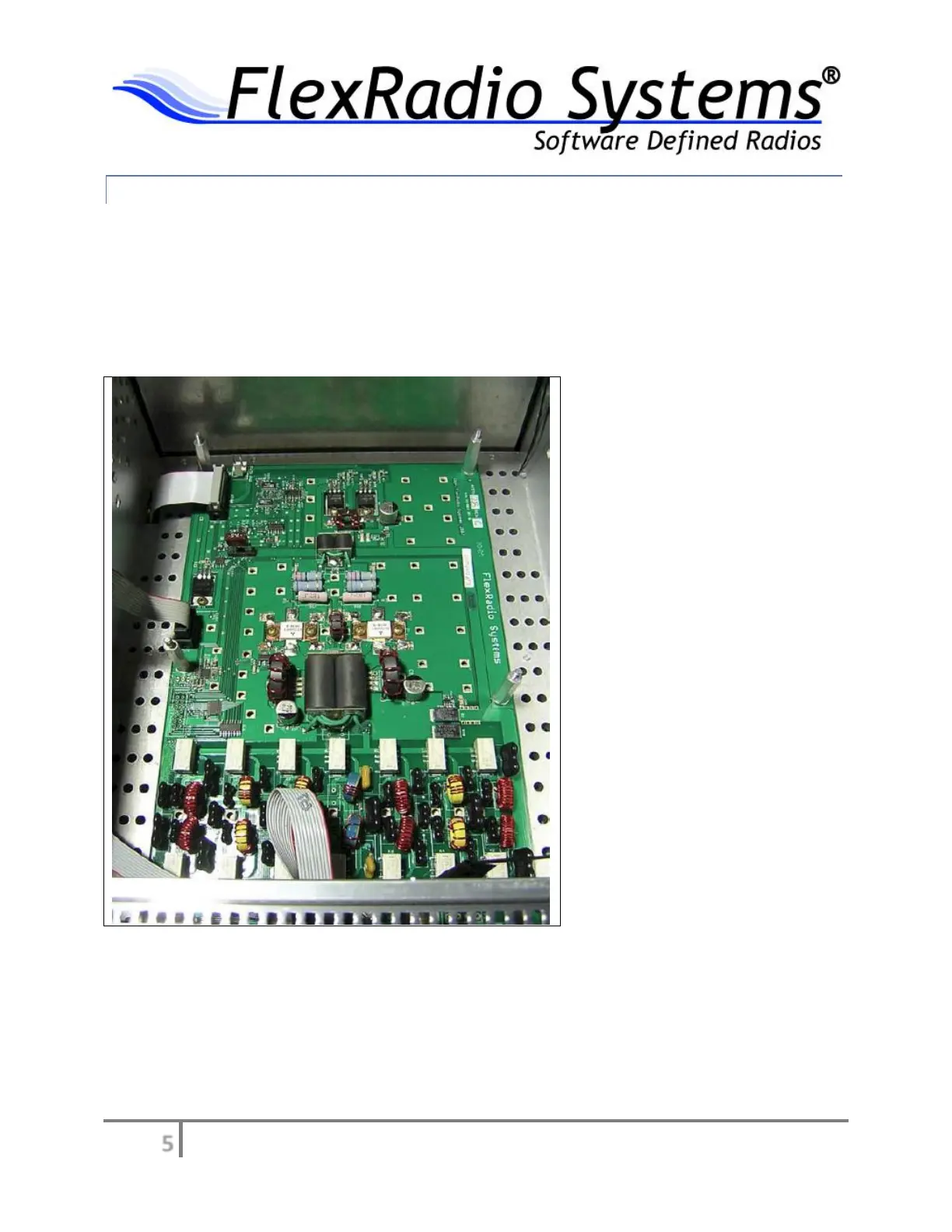
Figure 5 – PA with 3/4” spacers installed
c. Plug one end of the ATU control ribbon cable into the small keyed connector marked “SV2” on the center right
hand edge of the PA board. When inserting the ribbon cable, insert the plug end of the cable into connector SV2
so that it protrudes inward from the plug towards the PA board and the red strip of the cable is oriented towards
the front of the FLEX-5000. You can see the smaller ribbon cable properly plugged into SV2 on the left side center
of the PA board in Figure 5 above, just behind the 3/4” (1.9 cm) spacer. Lay the cable over the side of the FLEX-
5000 chassis as shown in Figure 5 so that it does not get in the way when installing the RF shield and ATU board.