2009-06-25 2/4 400-610-010-A
NOTE: Using an ohmmeter, verify the sensor’s integrity. It
must read between 8 to 12 K Ohms in order to obtain
temperature readings between 20°C and 30°C (68°F to
86°F).
• Insert the sensor wires through one of the two openings on the
power base and connect them to terminals 1 and 2 (no polar-
ity).
• The wire must be centered between the heating cables at a
distance of 30 to 60 cm (1 to 2 ft.) within the heating zone. Do
not cross the probe wire over the heating cables.
• The sensor should be placed in a neutral location, not near any
other heating or cooling sources.
• Secure the sensor to the floor using hot glue. It is necessary to
embed the sensor in the floor surface so it is at the same level
as the heating cables.
4) Connect the Econo Input (optional)
The thermostat is equipped with an Econo input which allows
connection of any remote control device equipped with a dry
contact. For more information, see the section on Vacation mode.
Insert the wires (use an 18 to 22 gauge flexible wire cable) through
one of the two openings on the power base.
Connect one end of the wires to terminals 2 and 3 of the power
base and the other end to the dry contact of a remote control device
(no polarity).
5) Set the DIP switches
The control module has four DIP switches to select the following
options:
Time and Temperature
Display (1)
•°F/12h
• °C/24h (default)
Early Start (2)
• E.S. On
• E.S. Off (default)
This function determines the
optimal system start time to obtain the desired temperature by the
set time. When this function is enabled, the system can be acti-
vated a few hours before the program’s start time.
Temperature Control (3)
This model offers the following three types of temperature control:
Permanent Backlight (4)
• P.B. On (The display remains lit all the time.)
• P.B. Off (Default. The display is lit for 12 seconds when the
adjustment ring or any button is pressed.)
6) Complete Installation
Install the power base onto the electrical box using the provided
screws and return the control module on the power base. Apply
power to the floor heating system.
NOTE: Keep the thermostat's air vents clean and free from
obstructions.
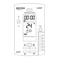
7) First Power On
When power is applied for the first time, the
screen displays 0:00 MO (Monday) as well as
the ambient/floor temperature.
If a problem occurs, one of the following mes-
sages will be displayed:
LO: the temperature is below 0°C (32°F) The heating indicator is
displayed and the system is activated.
HI: the temperature is above 70°C (158°F).
Er: the floor sensor is not connected properly or defective
(F temperature control) or the ambient sensor is defective
(AF temperature control).
To verify if the thermostat detects the floor sensor, select the
F temperature control (see DIP Switch Configuration). If the screen
displays Er, the floor sensor is not connected properly or defective.
If the screen displays the temperature, the sensor works.
9) Setting the Time and Day
n Press D, H or M to access the menu.
o Press H and M to set the time.
p Press D to select the day.
q Press MODE/RET to exit.
NOTE: If you remove the module from its base for more than
6 hours, the time and day must be reprogrammed.
This thermostat has a built-in Ground Fault Circuit Interrupter
(GFCI). In the event of a ground fault, the GFCI trips and quickly
stops the flow of electricity to prevent serious injury.
Definition of a ground fault
Instead of following its normal safe path, electricity passes through
a person’s body to reach the ground. For example, a defective floor
heating mat can cause a ground fault.
The GFCI does not protect against circuit overloads, short circuits,
or electrical shocks. For example, you can still receive an electrical
shock if you touch bare wires while standing on a non-conducting
surface such as a wood floor.
Ground Fault Protection Reset
When the GFCI trips, the TEST button illuminates (red) and GFI
appears on the screen. To reset the GFCI, switch the thermostat to
OFF and back to ON. The TEST button light will go off and GFI will
disappear.
If the TEST button illuminates and GFI appears on the screen
during normal operation, check if the fault has been caused by an
external interference such as a halogen light or an electric motor. In
this case, reset and test the GFCI. However, if the fault occurs
again for unknown reasons, cut power to the floor heating system
from the main electrical panel and have the installation verified by
an electrician.
GFCI Test
To ensure the GFCI is always in working order, test it once the ther-
mostat is installed and every month thereafter.
n Increase the temperature sufficiently to start heating.
o Wait for about 5 seconds until the heat intensity indicator ( )
appears on the screen.
p Press the TEST button at the top of the thermostat.
• If the TEST button does NOT illuminate, the test has failed.
Cut power to the heating system at the main electrical panel,
Temp. control Switch position Notes
Ambient
with floor limits
DOWN (AF) Requires a floor sensor
Floor (default) UP (F) Requires a floor sensor
Ambient DOWN (AF)
Use only when floor sensor is not installed.
Not recommended for floor heating
GROUND FAULT CIRCUIT INTERRUPTER
400-610-010-A (Flextherm FLP12 prog CAN) ENG.fm Page 2 Thursday, June 25, 2009 1:20 PM
 Loading...