2009-06-25 1/4 400-610-010-A
The FLP12-GA programmable thermostat, specially designed for
floor heating installations, is equipped with two ultra-precise sen-
sors which allow temperature control by separately monitoring both
floor and ambient settings, thus providing greater comfort.
Installation Guidelines
To avoid electrical shock, turn off power to the heating system
at the main electrical panel. The installation must be performed
by qualified electrician.
Install the thermostat on an expanded (deep) electrical box.
Choose a location about 1.5 m (5 ft.) above the floor and on an
inside wall.
Avoid locations where there are air drafts (top of staircase, air
outlet), dead air spots (behind a door), direct sunlight or con-
cealed chimneys or stove pipes.
Supplied Parts
One (1) thermostat (control module and power base)
Two (2) screws
One (1) 4.6 m (15 ft.) floor sensor
One (1) flat-tip screwdriver
Four (4) solderless connectors for copper wires
NOTE: Special CO/ALR solderless connectors must be used
when connecting with aluminum conductors.
1) Separate the control module from the power base
Loosen the screw and separate
the control module from the
power base. The screw
remains captive on the power
base.
2) Connect the thermostat wires
Connect the thermostat to the floor heating system (load) and to the
power supply
using solderless connectors for copper wires.
The floor heating braided shields or green wire as well as the power
supply copper ground wires must be secured to the ground terminal.
3) Connect the floor sensor
INSTALLATION
L2(N)
L1(L)
L2(N)
L1(L)
Floor heating system
Power supply
Red
Red
(White)
Red
Black
Black
Black
240 V (120 V)
Floor sensor
To remote control device (see section 4)
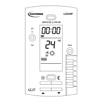
FLP12-GA
User Guide
Current program number when
Automatic mode is activated
Room or floor
temperature.
Arrow indicates
a setpoint
Indicates the amount
of power sent to the
floor heating system
Vacation
mode
Time and day
Economy setpoint
Manual
mode
Temperature
adjustment
ring
Day setting
To program
and view the
schedule
Comfort,
Economy
and Vacation
setpoints
Time setting
To clear a
program
To select a
mode or to exit
programming
mode
Comfort setpoint
Floor
minimum
and
maximum
temperature
(AF only)
GFCI test button
and light
To enable/disable heating
and to reset the GFCI
400-610-010-A (Flextherm FLP12 prog CAN) ENG.fm Page 1 Thursday, June 25, 2009 1:20 PM