Document Title Document No. Revision
Date Section
Supplement S3 to the AMM CTLS-LSA –
CTLS-LSA with ROTAX 912iS
AF 0480 0011 00 05-Aug-12 71-00-5
Approval Ref.: Approved on the Basis of Manufacturer Self Declaration
71-00.3.2.1 Type of Maintenance
Line
71-00.3.2.2 Minimum Level of Certification
Repairman, Light Sport Aircraft-Maintenance (RLSA-M) or higher
71-00.3.2.3 Procedure
A. Recommended Special Tools and Parts
Item Quantity Unit
Padded support 1 Pcs
B. Engine Mount Inspection
Step Action Reference
1 Remove upper and lower cowlings 71-00.3.1
2
Lift the forward fuselage by pushing down the tail at the narrowest part so that
the Nose Wheel is at least 25 cm (10 inch) off the ground.
3
Insert the padded support securely just behind the firewall (under the fuselage
bottom).
4
Inspect the Engine Mounts 1 and 2 for deformations, cracks, paint delaminating,
corrosion, loose hardware, chafing by cables, wires, hoses, etc., and make sure
that any flexible item is secured to the engine mount.
5 Inspect the rubber Shock Mounts for porosity, cuts, damage and deformations.
6
Inspect the presence of lock wire on engine mounting Screws M10 item 14.
Replace safety wire if necessary.
7
Inspect engine mounting screws for condition and tightening. Check markings of
marked bolts, remove safety wire and re-torque bolts that are safety wired. Re-
install safety wire when done and where applicable.
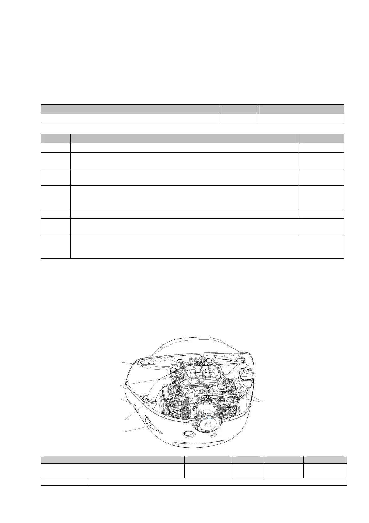
71-00.3.3 Air Intake Inspection
Air is fed into the engine from a NACA inlet at the right side of the lower cowling, through a
cylindrical air filter installed in the filter box at the lower cowling and through throttle body
socket which fills airbox with sufficient airflow.
Airbox is equipped with two pressure sensors and two temperature sensors for both
injection manifolds.
Air intake to fuel injectors flow through intake manifolds. This process is controlled by
ECU, and provide optimized fuel consumption.
Fig. 71-00-3. Air Intake System
Airbox
Intake
Manifold
Clamp
Lower Cowling
Aeroduct Hose
NACA inlet
 Loading...