3
INTERCOM INSTALLATION
For In-panel or Under-panel Mount: The intercom box measures 2.375"W x 1"H x 2.625"D. Depending on the type of housing used on your
selected DB25 connector, allow at least an additional 3/4" in depth for mounting. If you’re using the Flightcom supplied DB25 connector, allow
an additional 2" in depth. The intercom can be placed either vertically or horizontally in the instrument panel, under the panel, or in any other
suitable location in the aircraft.
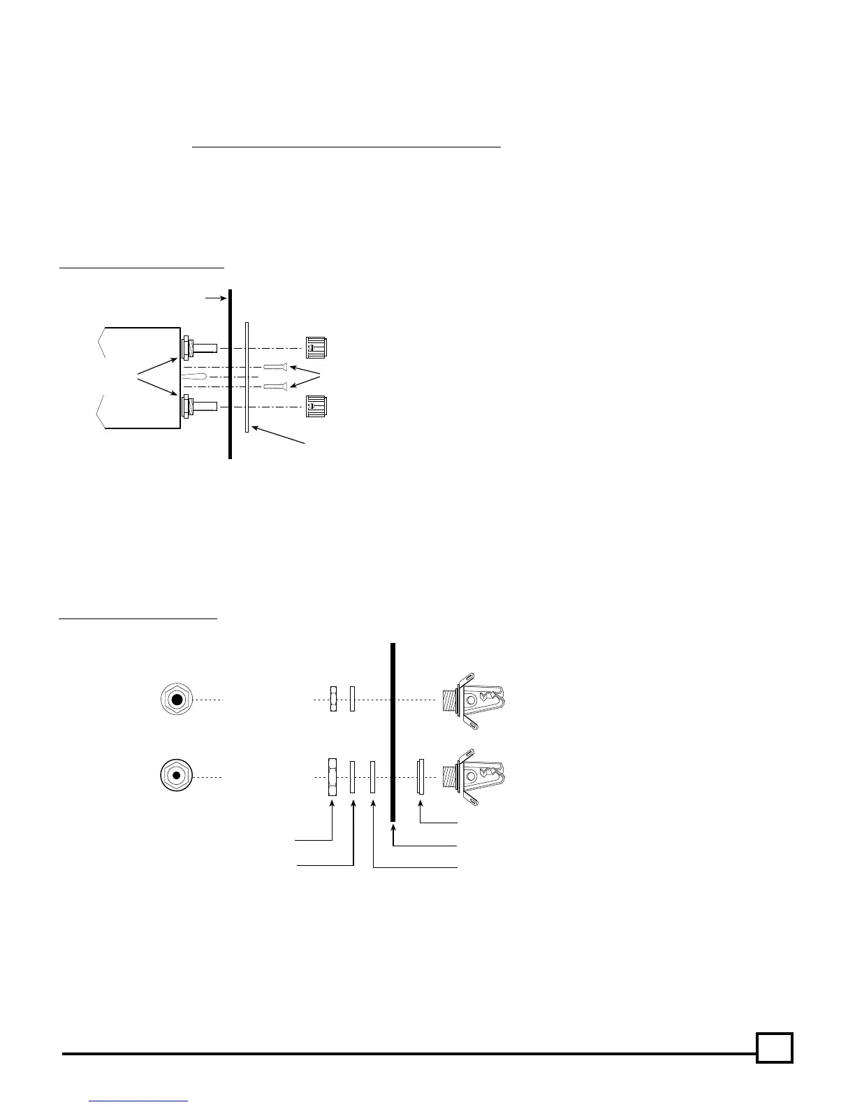
For In-panel Mounting: Leave the two potentiometer nuts in place on the intercom. Mark the panel by placing the front panel plate in the
location of your choice, either vertically or horizontally, and trace the hole location for drilling.
For panels less than .1" thick (Drill Template #1 — See figure 10) use a 9/32" drill for the controls. For panels between .1" and .2" thick (Drill
Template #2 — See figure 10) use a 1/2" drill or punch so the nuts can be cleared.
Insert the intercom through the panel and the faceplate of your choice and install the two 4-40 x 1/2" mounting screws. DO NOT USE ANY
REPLACEMENT SCREWS LONGER THAN 1/2 INCH! Install knobs so that the mark points to the 7 o’clock position when fully counter-clockwise.
Headphone Jack (Large ID)
Mic Jack (Small ID)
AIRCRAFT PANEL
WASHERS
HEX NUTS
SHOULDER WASHER (Mic Jack Only)
INSULATING FLAT WASHER
TOP VIEW
SIDE VIEW
Drill 3/8" Hole
Drill 1/2" Hole
Fig. 8 Jack Mounting Diagram
(Headphone and microphone jack info continued next page.)
Fig. 7 Control Panel Installation
INTERCOM
AIRCRAFT PANEL
INTERCOM
FRONT PANEL
Knob
4-40 Screws(2)
Knob
DO NOT
Remove
These Nuts
Headphone and Microphone Jacks: Choose a location for each pair of jacks (one microphone, one headphone) for each station, up to a total
of 4 stations. Carefully mark each location. Drill a 3/8" hole for each headphone jack and a 1/2" hole for each microphone jack/shoulder
washer. Connect the jacks with the proper wire and according to the wiring diagram on page 7.
The intercom microphone jacks must be insulated from the airframe, but the headphone jacks may either be grounded to the airframe or
insulated with a separate ground wire running back to the intercom.
Note: Do not use the same ground wire for the headphone and microphone jacks.
Note:
Use the two flathead screws when mounting the
horizontal faceplate. Use the two panhead screws when
mounting the vertical faceplate.