5
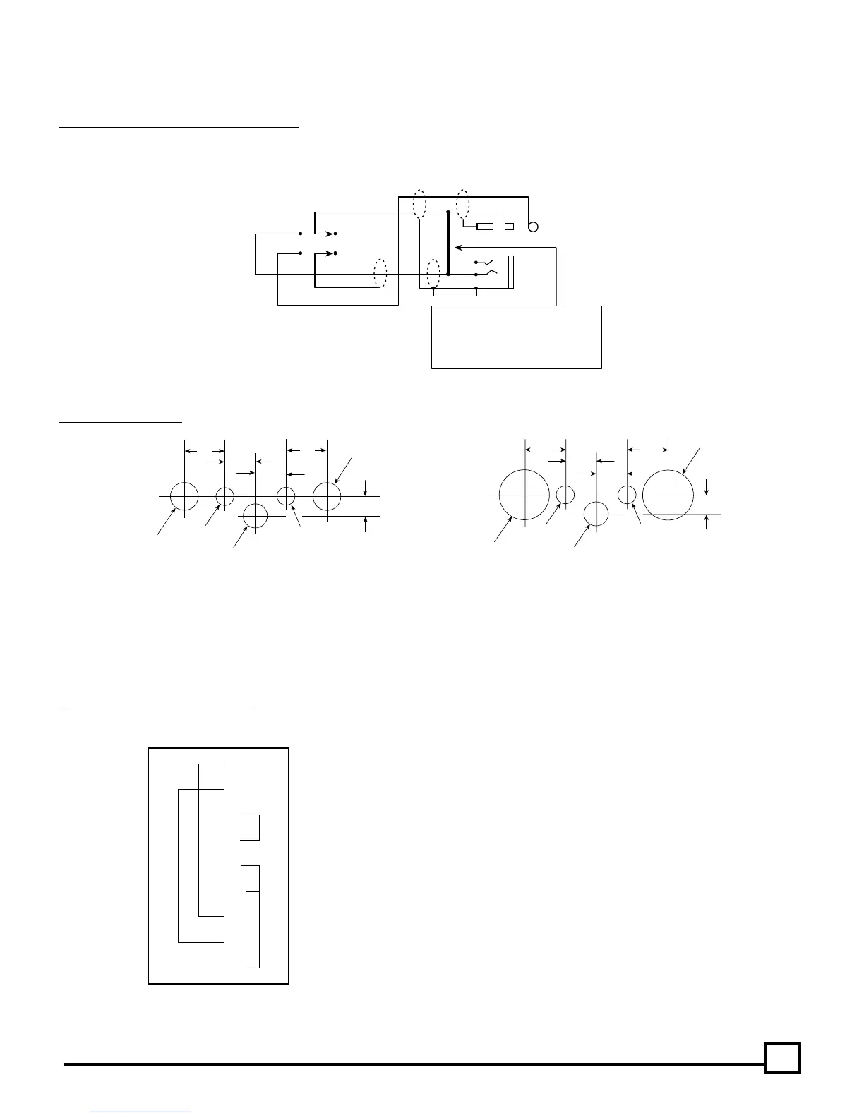
PTT
Modification to double-pole
push-to-talk switch for use
with installation.
ADD CONNECTION
Mic audio needs to go straight through and not be switched. Make modification inside the in-line jack or switch housing. Use a continuity tester
to locate the wire from the ring connector of the mic plug.
Fig. 9 PTT (Push-to-Talk) Switch Modification
Fig. 10 Drill Templates
.185"
.4" .4"
.3"
.3"
9/32"
9/32"
3/16"
1/4"
3/16"
DRILL TEMPLATE #1
(For panels less than .1” thick)
.185"
.4" .4"
.3"
.3"
3/16"
1/4"
3/16"
DRILL TEMPLATE #2
1/2"
1/2"
(For panels between .1” and .2” thick)
PROCEDURE FOR WARRANTY CLAIM
Please send in your warranty card promptly. When returning a unit for repair, enclose a copy of your original, dated bill of sale or the installation
certificate as proof of purchase. Defective units must be shipped to us with the freight prepaid.
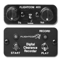
In the event that you need to remove your intercom for service, we suggest the following wiring as a by-pass plug, so that radio audio may still
be heard, even when the intercom is removed.
Fig. 11 By-Pass Plug Wiring Diagram
1
2
7
8
9
11
13
17
21
DB25-f