Do you have a question about the FLIR VT8 Series and is the answer not in the manual?
Overview of VT8 Series capabilities including AC/DC Voltage, Current, NCV, and key features like Data Hold, Relative/Zero, Worklight, and APO.
Device component for detecting AC voltage without direct contact.
Dial for selecting measurement modes like Voltage, Current, Resistance.
Button to cycle through measurement functions or AC/DC options within a selected mode.
Used to enter/exit Relative mode or zero the display.
Freezes readings and controls the intensity of the LCD backlight.
Details on switch positions for OFF, AC/DC Current, AC/DC Voltage, NCV, and Resistance/Continuity/Capacitance.
Explanation of display icons and readings including Auto Range, Data Hold, Relative mode, and units.
Diagram illustrating how to connect the meter for AC/DC Voltage measurements.
Diagram showing the correct method for measuring AC/DC Current using the clamp.
Illustration of how to use the NCV function to detect voltage.
Visual guide for measuring resistance, continuity, and capacitance.
Instructions for safely replacing the meter's batteries.
Contact details for technical support, service, and repair via website, email, and phone.
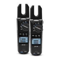
The FLIR VT8 Series of Voltage, Continuity, and Current Testers, including models VT8-600 and VT8-1000, are True RMS devices designed for comprehensive electrical measurements. These testers are capable of measuring AC/DC Voltage, AC/DC Current, Resistance, Continuity, and Capacitance. A key safety feature is the integrated Non-Contact Voltage Detector (NCV), which allows users to detect voltage without direct contact, enhancing safety during electrical work.
The design of the VT8 Series emphasizes user convenience and functionality. Each device features a clear LCD display that provides real-time measurement readings. The display is backlit, which is particularly useful for working in dimly lit environments. The backlight offers two intensity levels, allowing users to adjust it based on ambient light conditions to conserve battery life. An auto power off (APO) function is also included, automatically turning off the meter after 15 minutes of inactivity to save battery power.
For data management, the VT8 Series includes a Data Hold function, enabling users to freeze the current reading on the display for easier recording or review. The Relative/Zero mode is another useful feature; for ACV/DCV, ACA, and Capacitance measurements, it allows users to set a reference point and display subsequent readings relative to that point. For DCA measurements, a short press of the REL/ZERO button will zero the display, while a long press exits this mode.
The device's interface is designed for intuitive operation, primarily through a rotary function switch and several push buttons. The rotary switch allows users to select the desired measurement function, such as AC/DC Current, AC/DC Voltage, Non-Contact Voltage Detection, or Resistance/Continuity/Capacitance. The MODE button is crucial for toggling between AC and DC measurements when the rotary switch is set to Voltage or Current, and for selecting specific functions within the Resistance/Continuity/Capacitance mode.
A worklight button is integrated into the design, providing illumination for the measurement area, which is beneficial when working in dark or confined spaces. This feature, combined with the backlit LCD, ensures visibility of both the work area and the display.
The meter's display provides a wealth of information at a glance. It indicates the auto range status, data hold activation, relative mode, and DCA zero. The NCV icon illuminates when non-contact voltage is detected, and additional icons show electrical signals detected, APO active status, and battery status. The main display digits show the measurement value, accompanied by a minus sign for negative readings, and icons for DC (direct current) and AC (alternating current). Unit of measure and function icons are also clearly displayed, such as MΩ, µF, V, and A, to provide context for the readings.
In terms of usage, the VT8 Series is straightforward. To power on the meter, the rotary switch is moved from the OFF position to any other function. If the meter fails to power on, it indicates that the batteries may need replacement. The APO function ensures that the meter conserves power when not in active use.
Maintenance of the VT8 Series primarily involves battery replacement. When the battery status indicator on the LCD shows low power, or if the meter fails to power on, the batteries should be replaced. This process requires turning the meter off, disconnecting all test leads, and removing the rear compartment screw to access the battery compartment. The device uses two 'AA' batteries, and it is important to observe correct polarity during replacement. After replacing the batteries, the meter should be reassembled before further use.
The robust construction and comprehensive feature set of the FLIR VT8 Series make it a versatile tool for electricians, technicians, and DIY enthusiasts who require reliable and safe electrical measurements in various applications. The VT8-600 and VT8-1000 models are designed to meet different voltage and current requirements, offering flexibility for a range of professional and personal uses.
| Temperature Range | -10 to +450°C (14 to +842°F) |
|---|---|
| Accuracy | ±2°C (±3.6°F) or ±2% of reading |
| Image Frequency | 9 Hz |
| Focus | Focus Free |
| Display | 2.8 in. (71 mm) Color LCD (320 x 240 pixels) |
| Dimensions | 220 x 75 x 55 mm (8.6 x 3.0 x 2.2 in) |
| Weight | 350 g (12.3 oz) |
| Battery Type | Rechargeable Li-ion battery |
| Emissivity Correction | 0.1 to 0.99 |
| Drop Test | 2 m (6.5 ft) |
| Storage Temperature | -40 to +70°C (-40 to +158°F) |