Do you have a question about the FLIR Extech 412355A and is the answer not in the manual?
Details the physical components and controls of the calibrator, including the LCD and buttons.
Instructions for replacing the meter's 9V battery when the LOW BAT message appears.
Provides instructions for the proper disposal of used batteries and the device itself.
Explains how to turn the unit on/off and manage the automatic power-off feature.
Guides on using the function slide switch to select Voltage or Current modes.
Instructions on selecting between SOURCE (output) and MEASURE (input) modes.
Details on using the UNIT button to select voltage (mV/V) or current (mA/%).
How to use buttons to increase/decrease output values in specific digit steps.
Procedure for manually zeroing the display in the MEASURE mode.
Steps to recall and use pre-set memory values for stepped calibration outputs.
Guide to storing custom output values into the meter's nonvolatile memory.
Lists and explains how to reset the meter to its factory default memory values.
Explains how the meter indicates readings outside the specified range with HHHH or LLLL.
Detailed steps for using the calibrator to measure voltage or current input.
Detailed steps for using the calibrator to source voltage or current output.
Covers general performance metrics, power, dimensions, weight, and accessories.
Details the measurement and sourcing ranges, resolution, and accuracy for various functions.
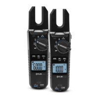
The Extech Model 412355A is a Current/Voltage Calibrator, part of the Oyster Series, designed for both measuring and sourcing current and voltage. This device features a convenient flip-up display and comes with a neck-strap, allowing for hands-free operation. It is shipped fully tested and calibrated, ensuring reliable performance with proper use.
The calibrator is equipped with a 9999 count LCD display that shows various readings and settings. It can operate in two primary modes: MEASURE (input) and SOURCE (output).
In MEASURE mode, the unit functions as a meter to measure voltage or current. Users can select between Voltage or Current using the Function switch, then press the MODE button to select MEASURE. The UNIT button allows selection of mA or % for current measurements. Once configured, the calibration cable is connected to the meter and the device or circuit under test, and the measurement is displayed on the LCD.
In SOURCE mode, the unit acts as a source to output voltage or current. Similar to MEASURE mode, the Function switch is used to select Voltage or Current, and the MODE button is pressed to select SOURCE. The UNIT button enables selection of V or mV for voltage, or mA or % for current. The calibration cable is then connected to the meter and the device or circuit under test. The output value can be adjusted using the UP and DOWN buttons, with the LCD displaying the current output level. Alternatively, stored calibration values from memory can be used. The current output range for -25% to 125% is 0 to 24mA.
The device includes a MEM button feature that provides five user-settable source values for stepped calibration outputs, available in Voltage, mA, and % in SOURCE mode. These memory values are stored in nonvolatile memory and are not erased when the unit is powered off. To source from stored values, the user selects SOURCE mode, then presses the MEM button to cycle through the M1 to M5 memory locations. The stored value for the selected location will be displayed and sourced. The "SOURCE" icon will blink if the output value has not reached a stable level, often due to high load impedance in current mode or low load impedance in voltage mode. To store a value, the user adjusts the display to the desired source value using the UP/DOWN buttons while a memory location is displayed, then presses and holds the MEM button for more than 2 seconds. The calibrator also has default memory values (e.g., 0mV, 2V, 4mA, 0% for M1) that can be restored by pressing and holding the POWER button for more than 4 seconds in SOURCE mode, which will briefly display "dFLt".
The ZERO button is used to manually zero the display in MEASURE mode. This is done by setting the meter to MEASURE mode, shorting the input jack, and then pressing and releasing the ZERO button.
The calibrator is designed for ease of use with several intuitive controls:
The device includes an Auto Power OFF (APO) feature that turns the meter off after 10 minutes of inactivity to conserve battery life. This feature can be overridden by pressing and holding the MODE button until the display shows "APO d" (APO deactivated) or "APO A" (APO activated).
Battery Replacement: The calibrator is powered by a 9V battery or an AC adapter. When the "LOW BAT" message appears on the LCD, the 9V battery should be replaced promptly to avoid inaccurate readings or erratic operation. To replace the battery, the calibrator's lid is opened, the battery compartment is opened using a coin at the arrow indicator, the old battery is replaced, and the cover is closed.
Disposal: Users are legally bound by battery ordinances to return all used batteries and accumulators to designated collection points; disposal in household garbage is prohibited. The device itself should be disposed of according to valid legal stipulations at the end of its lifecycle.
Over-range / Under-range Indication: Signals above or below the unit's ranges are indicated by "HHHH" for over-range and "LLLL" for under-range, providing clear feedback to the user.
| Category | Test Equipment |
|---|---|
| Model | 412355A |
| Continuity | Yes |
| Diode Test | Yes |
| Range | Auto |
| Power Source | 9V battery |
| DC Voltage | 600V |
| AC Voltage | 4V/40V/400V/600V |
| DC Current | 10A |
| AC Current | 10A |
| Resistance | 40MΩ |
| Frequency | 10MHz |
| Display | LCD |
| Measurement Units | V, A, Ω, F, Hz |