Do you have a question about the FLO-DYNAMICS BrakeMate and is the answer not in the manual?
Explains hazard levels indicated by signal words like DANGER, WARNING, CAUTION.
Details message types including hazard, avoidance, and consequences.
Provides graphical descriptions of potential hazards and how to avoid them.
Details DANGER, WARNING, and CAUTION levels of hazards and their implications.
Covers risks like unexpected vehicle movement, entanglement, fire/explosion, and associated precautions.
Addresses risks associated with battery acid, fire/explosion from batteries, and hot engine parts/fluids.
Outlines cautions for operation, misdiagnosis, and preventing equipment damage.
Lists the height, width, and depth of the BrakeMate machine.
Details power requirements and operating temperature range for the machine.
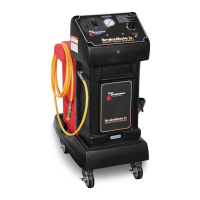
Highlights characteristics like durable body, ergonomic design, and clear sight tubes.
Identifies and describes key parts of the BrakeMate machine, including tanks, hoses, and wheels.
Lists and explains the function of each button on the control panel.
Explains the meaning of the LED lights on the control panel.
Guides through filling fluid, connecting cables, priming, and preparing the machine.
Covers master cylinder procedures and connecting to vehicle bleeder valves.
Describes how to select wheels and start the brake fluid flushing sequence.
Details disconnecting, adjusting fluid levels, testing, and draining the waste tank.
The BrakeMate is a fully automatic brake-flushing machine designed to service all four wheels of a vehicle in under nine minutes. This device aims to make brake service more profitable by eliminating the need for a second technician during brake bleeding. It provides a faster, easier, and more effective way to flush and pressure test a brake system, following OE recommended flushing sequences.
The machine features a control panel with several buttons and LED indicators for various operations. The "M/C PRESSURE" button pressurizes the master cylinder, ensuring no air enters the bleeder when screws are opened. The "ABS" button toggles the ABS function on and off. The "ENTER/START" button is used to enter a sequence wheel choice and initiate an exchange, while the "SELECT" button allows the user to choose the wheel sequence for the exchange. For fluid management, there's an "ADD FLUID/ DRAIN NEW TANK" button to pump new fluid out of the service hose, and a "DRAIN WASTE TANK" button to drain the waste tank. The "REMOVE FLUID" button has two functions: a single press pulls fluid through the ABS line, and a press-and-hold action pulls fluid through all five lines. The "PRIME" button purges air out of the service hose after the machine has been completely emptied of fluid. Finally, a "STOP" button is available to halt all operations.
LED lights on the control panel provide visual feedback on the machine's status. An "ABS" light indicates when ABS mode is turned on. A "WASTE TANK FULL" light signals that the waste fluid tank needs to be drained. A "NEW TANK EMPTY" light indicates that there is no more new fluid in the machine. A "RUNNING" light shows that the brake flush is in progress.
Setting up the BrakeMate involves filling the new fluid tank with fresh brake fluid and connecting the machine's battery cables to the vehicle's battery. Once powered on, a light on the front of the machine confirms the power connection. Before starting, all hoses should be placed on their resting ports, and the "PRIME" button should be pressed until fluid is visible in the yellow Tygon lines. After priming, the "STOP" button is pressed, and the ball valve on the service hose is closed. To relieve pressure on the red manifold after priming, the "REMOVE FLUID" button should be held down until all lights illuminate.
The process begins by draining the master cylinder. The ABS yellow Tygon line is removed from its holder, and a suction hose is attached. After removing the master cylinder cover and inserting the suction hose, the "REMOVE FLUID" button on the control panel is pressed. It's important to leave a small amount of fluid in the reservoir to prevent air from entering the system. Once sufficient fluid is removed, the "STOP" button is pressed.
Connecting to the master cylinder requires selecting and attaching the correct adapter from the kit. The yellow hose is then attached to the master cylinder adapter, ensuring the ball valve is open. The "M/C PRESSURE" button is pressed to pressurize the brake system, allowing bleeder screws to be opened safely without introducing air. It's crucial to ensure the pressure hose does not exert torque on the adapter to prevent leakage.
For connecting to the bleeder valves, the vehicle must be raised. All bleeder screws should be verified to open before attaching the Tygon lines. The Tygon lines are then attached to their respective bleeder fittings, and the bleeder screws are opened about 1/4 turn until fluid starts flowing into the yellow lines. The bleeder should remain open after the wrench is removed.
To begin the flushing process, the lights on the control board depicting the car's wheels will flash sequentially until a sequence is selected. The user selects a sequence by touching the "SELECT" button until the desired wheel is illuminated, then presses the "ENTER/START" button. This process is repeated until all wheels are selected. Pressing the "ENTER/START" button again after all wheels are selected initiates the flush.
After the flush, the machine is disconnected by first closing all bleeder valves on the vehicle. The "REMOVE FLUID" button on the machine is held down until the vacuum pump runs and all four wheel lights illuminate. The yellow Tygon lines are then removed from the bleeder fittings, and the vehicle is lowered. The ball valve on the pressure line is closed, and the line is carefully removed from the adapter using a rag. Finally, the master cylinder adapter is removed, and the fluid level in the reservoir is verified.
Adjusting the fluid level involves either topping off or removing excess fluid. To top off, the open end of a hose is connected to the yellow service hose, and the "ADD FLUID" button is pressed. The ball valve is slowly opened until the fluid reaches the correct level, and then the master cylinder cover is replaced. To remove fluid, the ABS line is removed from its holder, and a suction hose is attached. After removing the master cylinder cover and inserting the suction hose, the "REMOVE FLUID" button is pressed. The "STOP" button is pressed when finished, and the master cylinder cover is replaced.
After all operations, the vehicle should be started, and the brake pedal checked for a solid feeling. The waste fluid tank needs to be drained by connecting the machine's battery cables to a 12V power source. An open-end hose is connected to the black service hose and inserted into an appropriate disposal container. The ball valve is opened, and the "DRAIN WASTE TANK" button on the control panel is pressed.
Maintenance of the BrakeMate is straightforward. Users should ensure that debris is kept out of the new fluid and avoid spilling fluid on the control panel. Periodically, the exterior of the machine should be wiped down with a soft, damp cloth. Brake fluid is highly corrosive, so any spills must be cleaned up immediately, especially under the back of the machine where new fluid is filled.
| Model | BrakeMate |
|---|---|
| Manufacturer | FLO-DYNAMICS |
| Category | Service Equipment |
| Material | Steel |
| Type | Brake Bleeder |
| Hose Length | 12 ft |