Fig.7 Fig.8
<IT>
<GB>
<DE>
<FR>
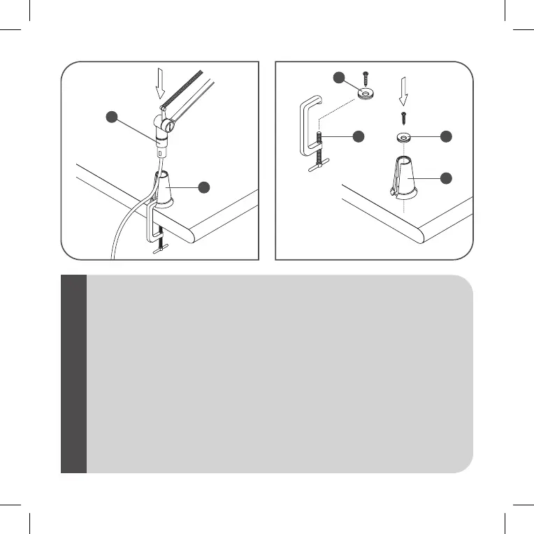
Fig.7MORSETTO- Inserire il corpo (C) nel supporto (F). Fig.8 NOTABENE: per fissare direttamente, sul piano di
appoggio, il supporto (F): svitare la bussola (H) dalla struttura del morsetto (I). Inserire la bussola (H) sul fondo
del supporto (F). Serrare il tutto mediante una vite autofilettante TPS Æ 4,2 lunghezza minima 25 mm.
Fig.7CLAMP- Insert the body (C) in the support (F). Fig.8 NOTE: to fix the support (F) directly on the backing
surface: unscrew the bush (H) from the structure of the clamp (I). Attach the bush (H) to the bottom of the
support (F). Lock the assembly in place with a self-tapping screw TPS Æ 4.2 at least 25 mm long.
Abb.7KLEMME- Den Körper (C) in die Halterung (F) einsetzen. Abb.8 BEACHTENSIE! für die Befestigung der
Halterung (F) direkt auf der Auflagefläche: Die Buchse (H) aus der Struktur der Klemme (I) schrauben. Die
Buchse (H) in den Boden der Halterung (F) einsetzen. Alles mit selbstschneidenden Senkkopfschrauben Æ 4,2,
Mindestlänge 25 mm befestigen.
Fig.7ETAU-Introduire le corps (C) dans le support (F). Fig.8
NOTE:
pour fixer directement le support (F) sur le
plan d’appui: dévisser la douille (H) de la structure de l’étau (I). Placer la douille (H) sur le fond du support (F).
Serrer le tout au moyen d’une vis autotaraudeuse à tête plate conique Æ 4,2 longueur mini 25 mm.
C
H
HI
F
F