5
NT 3000 Series Electro-Pneumatic Transducer Module FCD VLENIM0047-05 - 01/10
flowserve.com
Figure 2 – NT 3000 Transducer Schematic
Diaphragm
Flapper
4-20 mA
Input
Circuit
Board
Pressure
Modulator
3-15 psi
Output
Supply
Replaceable
Filter Element
Internal
Regulator
Gauge
Pressure
Sensor
Figure 3 – NT 3000 Transducer Orifice Screw
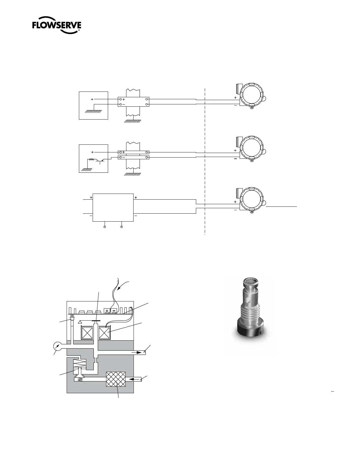
Figure 1 – Intrinsically Safe Installation Schematic
Grounded Supply
Source
Earth
FM Approved
Barrier
Floating Supply
Source
Earth
FM Approved
Barrier
Source
FM Approved
Isolating Repeater
Repeater
NT
3000
NT
3000
NT
3000
Non-hazardous Area Hazardous Area
V
t
or V
oc
< V
max
I
t
or I
sc
< I
max
C
a
C
i
+ C
cable
L
a
L
i
+ L
cable
Maximum
non-hazardous
voltage must
not exceed 250 V
FM/CSA
V
max
= 30 VDC
V
max
6.5 VDC*
I
max
= 125 mA
C
i
= 0 µF
L
i
= 1 µH
ATEX
U
i
= 28 V
I
i
= 120 mA
P
i
= 0.84 W
C
i
= 0 µF
L
i
= 0 µH
SAA
U
i
= 30 V
I
i
= 125 mA
P
i
= 0.8 W
C
i
= 0 µF
L
i
= 2 µH
For
* C
i
= 0 µF
Class I, Division 2. Applications must be installed as specified in NEC Section 501-4
when barriers are not used. (Refer to ANSI/ISA RP12.6 for guidance on installation.)
ANZEx
 Loading...