Do you have a question about the Flowserve Valtek MaxFlo 3 and is the answer not in the manual?
Instructions for unpacking, installation, and maintenance of Flowserve products. Emphasizes using products for their defined applications.
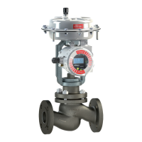
Instructions apply to Flowserve MaxFlo 3 control valves, covering installation and maintenance, but not all variations.
Defines safety terms like DANGER, WARNING, CAUTION, and NOTE used in the document for hazard identification.
Advises wearing protective clothing and ensuring valves are depressurized and cleaned before service operations.
Defines qualified personnel as authorized individuals with relevant knowledge for safe plant operation and maintenance.
Recommends using only original Flowserve spare parts and checking stored items for deterioration.
Emphasizes adhering to safety terms, avoiding unauthorized modifications, and refitting protective plates after service.
Advises storing Flowserve products in a clean, dry environment and keeping protective caps on flange faces.
Instructions for cleaning pipelines, ensuring alignment, and providing fire protection before valve installation.
Ensures correct valve installation by checking fluid flow direction indicated by an arrow on the body.
Safety warning about keeping hands, hair, and clothing away from the plug and seat when the valve is working.
Recommends upright actuator installation for easier maintenance and connecting air supply/signal lines.
Cautionary note about air filter orientation on valves to ensure proper performance.
Instructs to use specified bolts for pipeline installation and ensure proper gasket sealing capacity.
Advises providing overhead clearance for actuator disassembly and refers to the MaxFlo 3 Technical Bulletin.
Check for full stroke by varying instrument signal and observing plug position indicator for smooth movement.
Check all air connections for leaks and tighten or replace any leaking lines as necessary.
Check packing box bolting for proper tightness, cautioning against overtightening and recommending rechecking.
Ensure correct fail-safe direction by testing with air supply off and referencing actuator manual if needed.
Check for gasket leakage through end flanges and bonnet, re-torqueing bolts if necessary.
Examine the valve for damage caused by corrosive fumes or process drippings.
Clean the valve and repaint areas of severe oxidation.
Check packing-box for tightness, cautioning against overtightening and suggesting packing replacement for leaks.
If equipped with a lubricator, add lubricant if necessary.
Stroke the valve to check for smooth, full-stroke operation, indicating potential internal problems if unsteady.
Check positioner calibration and refer to the applicable positioner manual for further maintenance.
Ensure all accessories, brackets, and bolting are securely fastened.
Remove air supply to observe actuator for correct fail-safe action.
Check the actuator and all air connections for leaks.
Check and replace the air filter cartridge if necessary.
Safety warning to disconnect, depressurize, and drain the valve before disassembly to avoid serious injury.
Remove the actuator from the body by separating it at the yoke, referring to the actuator manual.
Remove the four bonnet nuts (item 114) from the valve body.
Remove the packing nuts and the gland flange (item 80) from the valve body.
Carefully pull the shaft out of the body, noting that bonnet, thrust bearing, packing stop, and packing slide out as an assembly.
Note that the plug is supported by the end post at this stage of disassembly.
Remove the end post nuts (item 119) and carefully remove the end post (item 122) from the body.
Remove the plug from the valve body.
Loosen packing-box nuts and slide the shaft out of the bonnet, removing thrust bearing and shaft stop spacer.
Remove the packing follower (item 87), packing (item 88), spacers (item 93), and packing stop (item 99).
Remove the bonnet gasket (item 58) and end post gasket (item 61), cleaning all bearing and seal surfaces.
Remove the shaft bearing (item 83) from the valve body, using a dowel if necessary, and avoid damaging it.
Unscrew the seat (item 30) using the appropriate tool, remove the seat (item 20) and adjustment shims (item 23).
Lubricate threads, bearings, and shaft shoulder with specified paste or lubricant before reassembly.
Always use new packing and gaskets when reassembling the valve to ensure proper sealing.
Ensure shaft, bonnet bore, and gasket surfaces are clean before reassembly to prevent contamination.
Ensure all bearing surfaces have been thoroughly cleaned before proceeding with reassembly.
Install all end post studs (item 115) and bonnet studs (item 108) into the valve body.
Insert the plug (item 50) into the body as shown in figure 2b.
Note that the end post bearing (item 84) is pressed into the plug.
Place the end post gasket (item 61) on the end post (item 122) and insert into the body, aligning with the plug.
Note for 3-inch valves and larger: orient end post with milled faces parallel to valve body flanges.
Tighten the end post nuts to finger tight.
Insert the shaft bearing (item 83) into the body until its shoulder contacts the step in the valve body.
Place the thrust bearing onto the shaft, sliding it up to the thrust runner.
Note for 10 and 12 inch sizes: an end spacer (item 47) is placed above the thrust bearing.
Place bonnet gasket and bonnet, orienting milled faces correctly, and push gently into the body.
Install packing stop, spacer, and packing into the bonnet as shown in figure 3.
Install bonnet nuts and tighten them to finger tight.
Install packing follower and gland flange, then tighten packing nuts to finger tight.
Tighten bonnet and end post nuts evenly, torquing to values specified in Table II.
Install shims and seat ring as described in the Seat Replacement section.
Install the actuator and yoke as described in the specific actuator installation manual.
Install the valve into the process line as described in the general installation section.
Warning: The actuator must be removed from the valve body before replacing the seat ring.
Loosen the packing box nuts to begin the seat replacement process.
Use the appropriate retainer tool to remove the seat retainer; tools are available from the factory.
Remove the seat and any shims that may have been installed underneath it.
Check both seat and plug surfaces for wear and galling; replace if necessary.
Clean seat ring, retainer, and body threads of old sealant residue for thorough cleaning.
Place seat without shims into body, rotate plug to 90 degrees open, and measure dimension 'A'.
Close the plug into the seat and measure dimension 'B' as shown in figure 4b.
For optimum sealing, do not over-rotate the plug into the seat; a slight under-rotation is recommended.
The difference between 'A' and 'B' indicates total shim thickness needed between the seat and valve body.
Remove seat, add correct shims, and use sealant. At least one shim is required regardless of valve size.
Lubricate retainer threads, tighten to contact seat, loosen 1/8 turn, cycle valve, then tighten per Table IV.
Illustrates recommended plug rotation, maximum limits, and avoided settings for optimal valve performance.
Provides a table for selecting shim thicknesses based on valve size and rounding rules for proper seat adjustment.
Lists required torque values and part numbers for seat retainer removal tools across different valve sizes and standards.
When remounting the actuator, refer to the appropriate actuator manual for detailed instructions.
Adjust actuator stroke stops correctly to avoid over-rotation and potential valve damage, especially with soft seats.
Install the valve in the pipeline according to the 'Installation' section and orientation recommendations.
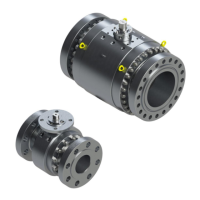
Highlights improvements in the anti-blowout system for greater safety, with shaft shoulder exceeding bonnet bore.
Explains how to upgrade from the old design by changing the bonnet and packing stop; contact Flowserve for parts.
Illustrates mounting orientations for diaphragm actuators with air-to-open configuration in various flow and pipe setups.
Illustrates mounting orientations for diaphragm actuators with air-to-close configuration in various flow and pipe setups.
Illustrates mounting orientations for cylinder actuators with air-to-open configuration in various flow and pipe setups.
Illustrates mounting orientations for cylinder actuators with air-to-close configuration in various flow and pipe setups.
Provides codes for Air Action, Pipe Configuration, Actuator Orientation, and Shaft Direction for valve mounting.
Addresses issues of excessive air bleeding from the transfer case and potential causes and corrections.
Troubleshoots jerky shaft rotation, including overtightened packing, lever arm adjustment, and lubrication issues.
Covers excessive leakage issues, focusing on external stroke stops, seat adjustment, and damaged parts.
Troubleshoots leakage through line flanges, addressing gasket surfaces, flange sealing, and pipe misalignment.
Addresses leakage through the packing box, including loose nuts, worn packing, and dirty components.
Troubleshoots valve slamming or water hammer, primarily relating to improper valve installation and flow direction.
Addresses issues where the shaft rotates but the plug remains open or closed, indicating a broken shaft.
Troubleshoots internal actuator failures where the actuator operates but the shaft does not rotate.
Addresses leakage from the bonnet joint or end post, focusing on bolting, gaskets, and surface cleanliness.
| Brand | Flowserve |
|---|---|
| Model | Valtek MaxFlo 3 |
| Category | Control Unit |
| Language | English |