6
VLENIM0006-03 (AQ) July 2019
Handle
Head K
Valve Size
(in)
Trim
No.
Handle Kit
No.*
Head
Kit No.
0.12
0.25
0.38
0.50
0.62
0.75
0.81
1.00 143434.999
1.5 1.25 143359.999 33/45
2 1.62 143360.999 60/82
3 2.62 143362.999 80/109
4 3.50 143361.999 135/184
6 4.00 165212.999
6
5.00
165215.999
*Handle lengths are 40 in long.
0.5–1.0
0.75–1.0
200/272
28/38
165088.999
165081.999
165217.999
Recommended
Torque
(ft-lb/N-m:+/-10%)
Bonnet
Bolt Size
(in)
Recommended
Bonnet Bolt Torque
(ft-lb/N-m; +/-10%)
Plug Head
Cap Screw
Size (in)
Recommended
Cap Screw Torque
(ft-lb/N-m; +/- 10%)
5/8
50 / 68 3/16
0.6 / 0.9
3/4
90 / 122 1/4
1.6 / 2.2
7/8
150 / 203 5/16
4 / 5
1
220 / 298 3/8
6 / 9
1-1/8
330 / 447 7/16
10 / 14
1-1/4
460 / 624 1/2
16 / 22
1-3/8
630 / 854 9/16
24 / 32
1-1/2 840 / 1140 5/8 33 / 45
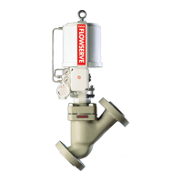
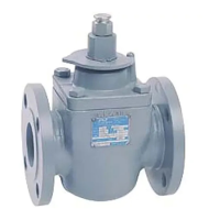
Figure 4: Mark Six seat removal tool
Table 2: Seat removal tools and seat torque values
Table 3: Bonnet bolting torques Table 4: Plug head bolting torques
11. Adjust stem engagement for air-to-open valves only, using the
following procedure.
NOTE: Proper stem engagement is essential on air-to-open valves
to provide stiff, stable operation as the valve throttles near the seat.
Cycle the valve to closed position. Observe plug position as
shown by the stroke indicator plate. This position is the bot tom of
the actuator piston stroke.
Cycle the valve to open position. Screw the plug out of the
actuator one-half turn. Cycle the valve to closed position. Observe
the plug position as indicated by the stroke plate. Repeat this
procedure, comparing plug position each time until the indicated
plug position is about 1/8 in above the initial or bottom position.
This procedure must be followed to assure stiff stable operation as
well as tight shutoff. Tighten all nuts evenly and completely, using
full wrench force to compress the gasket and seat the bonnet
metal-to-metal in the body. Proper tightness requires considerable
force; how ever, the bottoming of the parts metal-to-metal can
easily be felt through the wrench. Refer to Table 3 for the
recom mended torque values.
12. Tighten the stem clamp.
13. Tighten packing nuts to slightly over nger-tight.
14. Adjust stroke indicator position to indicate closed position when
valve is closed.
Removing the actuator, including yoke (without
disassembling the valve body subassembly)
1. Fully retract the plug until the stroke indicator is pointing to the
open position.
2. Loosen the stem clamp.
3. Loosen the gland ange.
4. Remove the yoke clamp (or yoke bolts if used).
5. Turn actuator completely off the plug and bonnet.
CAUTION: Do not allow the plug stem to rotate. Flats are
machined on the stem so it can be held with a wrench. Large
actuators may require a hoist. If a lifting ring is not provided,
use lifting straps around the yoke legs.
Reassembling the actuator, including yoke
1. Lift the plug off the seat and turn the actuator onto the plug. On
air-to-open valves, screw the actuator stem onto the plug stem as
far as it will go. On air-to-close valves, leave two or three threads
exposed.
CAUTION: Do not allow the plug to turn on the seat at any
time. Do not turn the plug in the bonnet. Flats are machined on
the plug stem so it can be held with a wrench.
2. Assemble yoke clamp or tighten yoke bolts.
3. Adjust the stem engagement for air-to-open valves only, according
to the procedure outlined in the “Reassembly of the Mark Six”
instructions, step 11.
4. Cycle the valve to closed position.
5. Slide the stem clamp on the actuator so that the bottom of the
stem clamp is ush with the bottom of the actuator stem. Check
to make sure the slits in the actuator stem are perpen dicular to the
stem clamp bolting.
6. Tighten the stem clamp.
7. Tighten the gland ange nuts evenly to slightly over nger- tight.