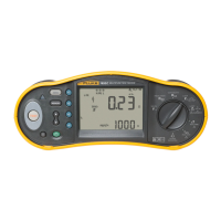
Electrical Installation Tester
Specifications
9
Insulation Resistance Measurement (R
ISO
)
Test Voltages
Model 1652C
Model 1653B
Model 1654B
ccuracy of Test
Voltage
(at rated test
current)
250-500-1000 V 50-100-250-500-1000 V +10 %, -0 %
Test
Voltage
Insulation
Resistance Range
Resolution Test Current Accuracy
50 V
10 kΩ to 50 MΩ 0.01 MΩ 1 mA @ 50 kΩ ±(3 % + 3 digits)
100 kΩ to 20 MΩ 0.01 MΩ ±(3 % + 3 digits)
100 V
20 MΩ to 100 MΩ 0.1 MΩ
1 mA @ 100 kΩ
±(3 % + 3 digits)
10 kΩ to 20 MΩ 0.01 MΩ ±(1.5 % + 3 digits)
250 V
20 MΩ to 200 MΩ 0.1 MΩ
1 mA @ 250 kΩ
±(1.5 % + 3 digits)
10 kΩ to 20 MΩ 0.01 MΩ ±(1.5 % + 3 digits)
20 MΩ to 200 MΩ 0.1 MΩ ±(1.5 % + 3 digits)
500 V
200 MΩ to 500 MΩ 1 MΩ
1 mA @ 500 kΩ
±10 %
100 kΩ to 200 MΩ 0.1 MΩ ±(1.5 % + 3 digits)
1000 V
200 MΩ to 1000 MΩ 1 MΩ
1 mA @ 1 MΩ
±10 %
Note
The number of possible insulation tests with a fresh set of batteries is 2000.
Auto Discharge
Discharge time constant <0.5 second for C = 1 µF
or less.
Live Circuit Detection Inhibits test if terminal voltage >30 V prior to
initiation of test.
Maximum Capacitive Load
Operable with up the 5 µF load.
No Trip and Hi Current Modes RCD/FI
Mains Input Voltage Range 100 - 500 V ac (50/60 Hz)
Loop Impedance: phase to earth Input Connection (soft key selection)
Line impedance: phase to neutral
Limit on Consecutive Tests Automatic shutdown when internal
components are too hot. There is also a
thermal shutdown for RCD tests.
Maximum Test Current @ 400 V 20 A sinusoidal for 10 ms
Maximum Test Current @ 230 V 12 A sinusoidal for 10 ms
Range Resolution Accuracy
[1]
10 Ω 0.001 Ω
Hi Current m mode: ±(2 % + 15 digits)
No Trip mode: ±(3 % + 6 digits)
20 Ω 0.01 Ω
Hi Current mode: ±(2 % + 4 digits)
No Trip mode: ±(3 %)
200 Ω 0.1 Ω
Hi Current mode: ±(2 %)
2000 Ω 1 Ω ±6 %
[2]
Notes
[1] Valid for resistance of neutral circuit <20 Ω and up to a system phase angle of 30 °. Test leads
must be zeroed before testing.
[2] Valid for mains voltage >200 V.

 Loading...