Fluke 433, 434, 435
Service Manual
3-10
Accuracy Check of Channel N (Neutral):
11. Connect the N input with the C/L3 input (See Figure 3-4). A/L1, B/L2, C/L3 now
give zero reading.
12. Set the Calibrator to 0 Hz / 0 V and then to OPR.
13. Fluke 433/434: check for a voltage readout V rms between 0.0 ... 0.6 V.
Fluke 435: check for a voltage readout V rms between 0.00 ... 0.12 V.
14. Check the 120 V range according to the table below.
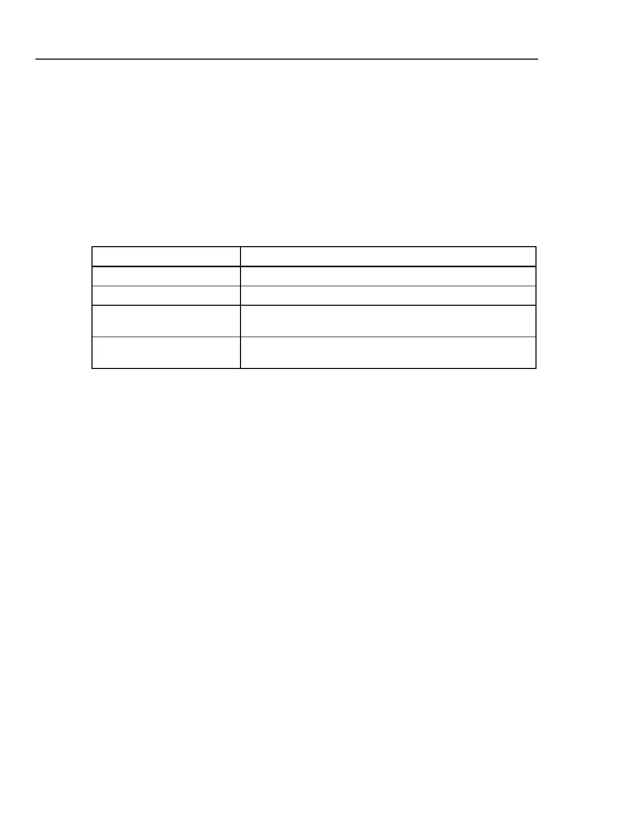
Table 3-4. Accuracy Check of Voltage Channel N (Neutral)
Set Calibrator to Readout at Voltage Channel N
0 Hz, 0 V, OPR Fluke 433/434: 0.0 ... 0.6 V, Fluke 435: 0.00 ... 0.12 V
60 V, 60 Hz, OPR Fluke 433/434: 59.4 ... 60.6 V, Fluke 435: 59.88 ... 60.12 V
120 V, 60 Hz, OPR Fluke 433/434: 119.4 ... 120.6 V, 59.99 ... 60.01 Hz
Fluke 435: 119.88 ... 120.12 V, 59.990 ... 60.010 Hz
240 V, 60 Hz, OPR Fluke 433/434: 239.4 ... 240.6 V, 59.99 ... 60.01 Hz
Fluke 435: 239.88 ... 240.12 V, 59.990 ... 60.010 Hz
15. Set the Calibrator to STBY.
Optional test. Bandwidth Check of Channel N (*):
16. Set the Calibrator to 120 V, 60 Hz and OPR.
17. Now check the voltage channel N. Use the Calibrator’s field edit function (5500A:
FIELD EDIT key, 5700A: AMPL/FREQ key) to adjust the Calibrator to an Analyzer
readout of 120.0 V / 120.00 V.
18. Increase the frequency to 3 kHz.
Fluke 433/434: check for a readout of 113.8 V or more.
Fluke 435: check for a readout of 114.00 V or more.
19. Set the Calibrator to STBY.
3.7.3 Verification of voltage inputs in 230 V range
Accuracy Check of Channel A/L1, B/L2, C/L3:
1. Set the Analyzer to 230 V, 50 Hz nominal (SETUP menu, arrow and ENTER keys).
Press MENU, select Volts/Amps/Hertz, press F5 - OK.
2. To check the A/L1, B/L2, C/L3 inputs: connect the N input to Ground (See Figure 3-
3).
3. Set the Calibrator to 0 Hz, 0 V and then to OPR.
4. Fluke 433/434: check for a voltage readout V rms between 0.0 ... 1.2 V.
Fluke 435: check for a voltage readout V rms between 0.00 ... 0.23 V.
5. Check the 230 V range according to the table below.