Fluke 433, 434, 435
Service Manual
4-10
2. The display must show step CL 0300.
If it does not, then press
F1
or
F2
to select the first calibration step in Table 4-
1.
3. Set the Calibrator output to source the signal 0 Hz, 0 V required for the calibration
steps in Table 4-1.
4. Set the Calibrator in operate (OPR) or standby (STBY) as indicated.
5. Press
F3
to start the calibration.
6. Wait until the display shows calibration status
:READY .
7. Press
F2
to select the next calibration step, and start the calibration.
Continue through all calibration points of Table 4-1.
8. When you are finished, set the Calibrator to Standby (STBY).
9. Continue at Section 4.6.2.
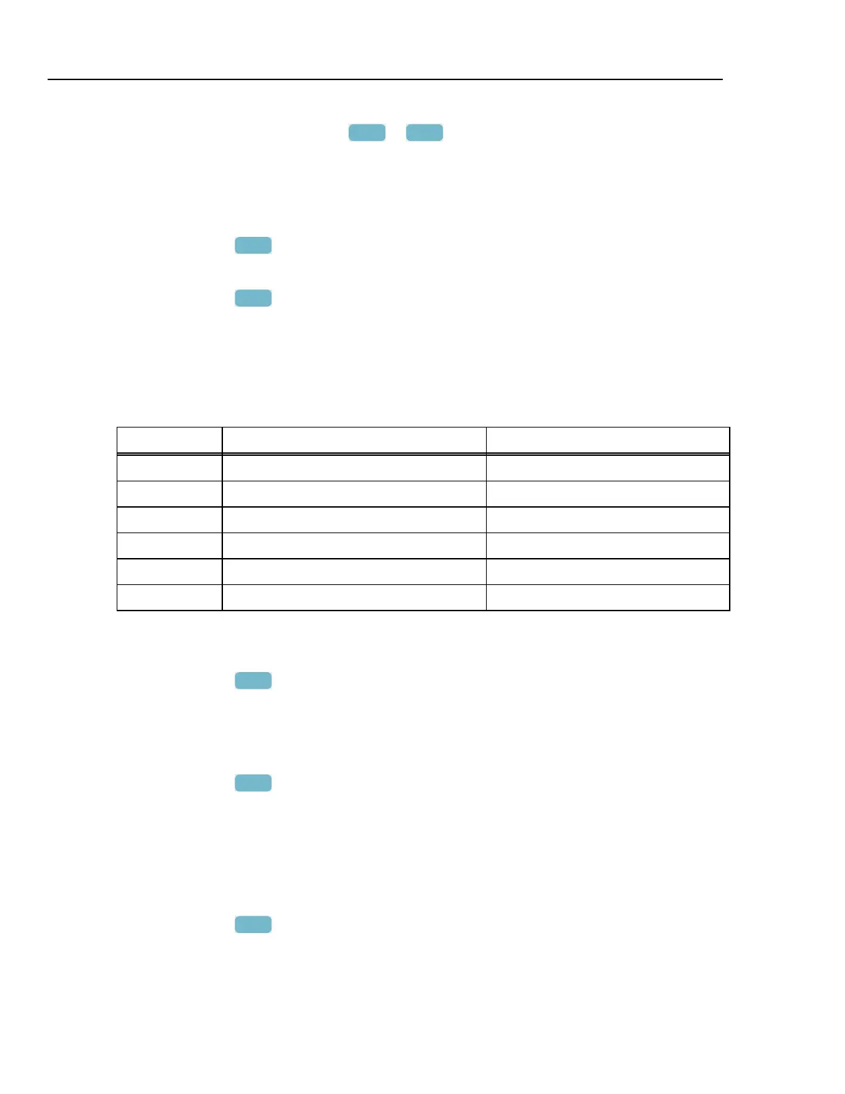
Table 4-1. Offset Adjustment of all Inputs
Cal step Description Calibrator Setting
CL 0300 OffsetLowVolt 0 V, 0 Hz, OPR
CL 0310 Offset125Volt 0 V, 0 Hz, OPR
CL 0320 Offset250Volt 0 V, 0 Hz, OPR
CL 0330 Offset500Volt 0 V, 0 Hz, OPR
CL 0340 Offset6KVolt 0 V, 0 Hz, OPR
--- --- STBY
4.6.2 Low voltage and current gain adjustment
Proceed as follows to do the Low Voltage and Current Gain Adjustment:
1. Press
F2
to select calibration step CL 0400.
2. Keep the Analyzer connected to the Calibrator as shown in Figure 4-3.
3. Set the Calibrator to source 0.67 V, 50 Hz .
4. Set the Calibrator to operate (OPR).
5. Press
F3
to start the calibration.
6. Wait until the display shows calibration status
:READY .
7. Set the Calibrator to Standby (STBY).
4.6.3 Voltage gain adjustment
Proceed as follows to do the Voltage gain Adjustment.
1. Press
F2
to select the first calibration step in Table 4-2 (CL 0410).
2. Connect the Analyzer to the Calibrator as shown in Figure 4-4: disconnect the current
inputs!