Disassembling the Analyzer
5.2. Disassembly & Reassembly Procedures 5
5-9
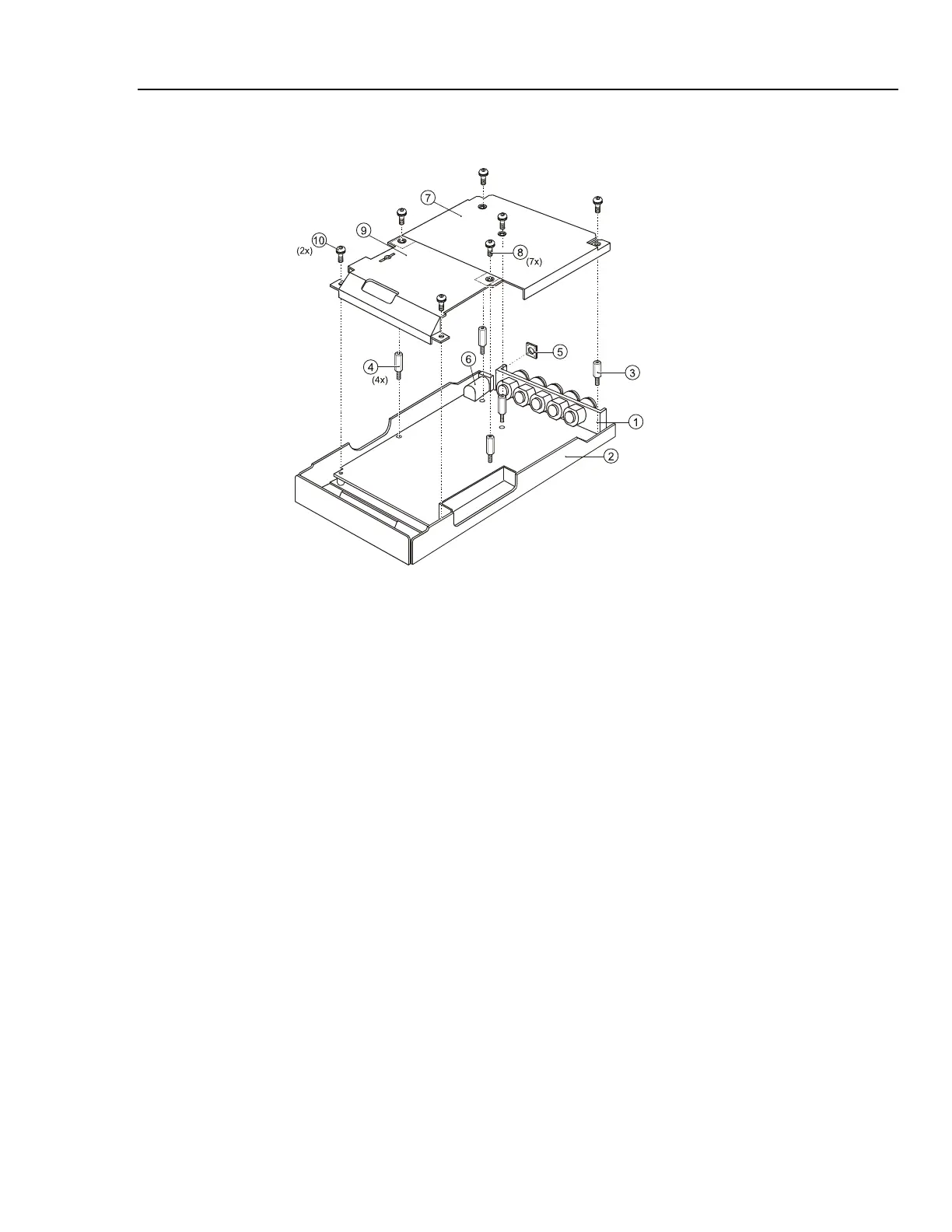
Figure 5-8. PCA Unit Assembly
5.2.10 Reassembling the Main PCA Unit
Reassembling the main PCA unit is the reverse of disassembly (see figure 5.8). However
you must follow special precautions when reassembling the main PCA unit.
1. Put the PCA in the shielding box, and fasten the 5 hexagonal standoffs (item 3,4).
2. Lock the shielding covers (item 7 and 9) and fix them with 7 M3x8 Torx screws.
Ensure that the small optical gate PCA mounted on the main PCA sticks through the
slot in the shielding cover (item 9).
3. Ensure that the rubber sealing ring (item 5) for the power connector is present .
5.2.11 Reassembling the Analyzer
Reassembling the Analyzer is the reverse of disassembly. However you must follow
special precautions when reassembling the Analyzer. Refer to figure 5-6.
Reassembling procedure for a completely disassembled unit:
1. Clean the inside of the lens with a moist soft cloth if necessary. Keep the lens free of
dust and grease.
2. Install the keypad item 3. Press the edges of the keypad into the sealing groove of
the top case. Ensure that the keypad lays flat in the top case, and that all keys are
correctly seated.
3. Install the keypad foil item 4. Align the positioning holes in the keypad foil to the
positioning pins in the top case.
4. Install the keypad support plate item 5.
5. Clean the display glass with a moist soft cloth if necessary. Install the display
assembly and its mounting frame, and fasten the 4 screws (item 8).