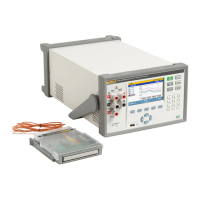
1586A
Calibration Manual
14
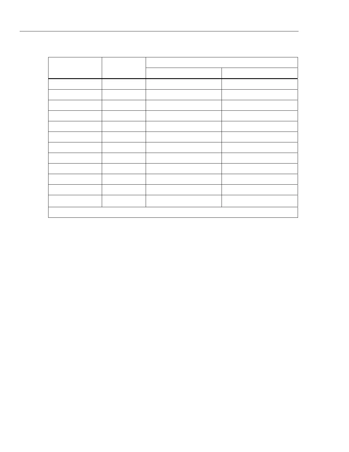
Table 7. DC Current Verification Steps
Nominal
Input (mA)
Range
1-Year Test Limits
High Low
0 0.1 3.5 nA -3.5 nA
0.1
[1]
0.1 100.0185 μA 99.9815 μA
-0.1
[1]
0.1 -99.9815 μA -100.0185 μA
0 1 11.0 nA -11.0 nA
1
[1]
1 1.000161 mA 0.999839 mA
-1
[1]
1 -0.999839 mA -1.000161 mA
0 10 0.35 μA -0.35 μA
10
[1]
10 10.00185 mA 9.99815 mA
-10
[1]
10 -9.99815 mA -10.00185 mA
0 100 3.5 μA -3.5 μA
100
[1]
100 100.0185 mA 99.9815 mA
-100
[1]
100 -99.9815 mA -100.0185 mA
[1] 5720A or 5522A must be used with 8508A to obtain suitable test uncertainty ratio.
1586-2586 CJC Module Accuracy Verification
1. Connect the calibrated E-type thermocouples to channel 10 on the Unit
Under Test (UUT).
2. Insert the thermocouples into a drywell calibrator which is set and stabilized
at 25 °C.
3. Configure the channels of the Product for an E-thermocouple.
4. Insert the reference thermistor probe into the drywell to measure the actual
temperature.
5. Use the reference thermometer with the reference thermistor probe and the
thermocouples with the Product to measure the drywell temperature until all
readings are stable.
6. Compare the thermocouple readings and reference thermometer reading.
7. The difference should be <0.6 °C.
 Loading...