Do you have a question about the Fluke 1586A and is the answer not in the manual?
Lists warnings and cautions for safe operation and handling of the product.
Details accuracy, ranges, and characteristics for various measurement types.
Instructions for setting the voltage selector and fuse for region of use.
Procedure for connecting the product to mains power.
Details how to turn the product on and put it into standby mode.
Guides users through configuring product settings via the Instrument Setup menu.
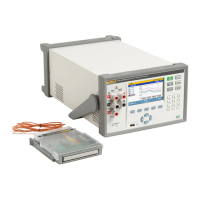
Step-by-step guide for installing input modules and relay cards.
Instructions for installing a DAQ-STAQ Multiplexer accessory.
Important safety precautions for wiring connections.
Instructions for configuring channels after inputs are connected.
Applying scaling calculations to measurement values.
Setting high and low limit alarms for channels.
Setting up scan parameters like trigger type and sample rate.
Defines when and how a scan starts and stops.
Steps to initiate a scan based on configured test setup.
Displays scan data and provides statistical analysis for each channel.
Visualizes measurement data in a graph format.
Measures a single channel between scan sweeps and views statistics.
Calibrates and verifies probes using an external temperature source.
Setting up temperature setpoints and test sequences for automated tests.
Saves scan or DMM measurement results to a file for PC transfer.
Transferring and viewing data files on a computer.
Using the DMM feature for voltage, resistance, current, and temperature measurements.
Configuring front-panel inputs for measurement type and range.
Procedure for replacing fuses and required part numbers.
How to clear data or reset the product to factory defaults.
Lists error codes, messages, causes, and solutions for diagnosing problems.
A chart with common problems, their causes, and solutions.
| Operating Temperature | 0 °C to 50 °C |
|---|---|
| Category | Scanner |
| Measurement Types | DC Voltage, AC Voltage, Resistance, DC Current, AC Current, Frequency |
| Thermocouple Accuracy | ±0.5°C |
| RTD Accuracy | ±0.05°C |
| Frequency Accuracy | ±0.01% |
| Input Isolation | 300 V |
| Display | Color LCD |
| Data Logging | Yes |
| Interfaces | Ethernet, USB, GPIB |
| Power | 100-240 VAC, 50/60 Hz |
| Accuracy | Varies by measurement type |
| Resolution | Varies by measurement type |
| DC Voltage Accuracy | ±(0.002% of reading + 0.0005% of range) (up to 100 V) |