1586A
Users Manual
3-8
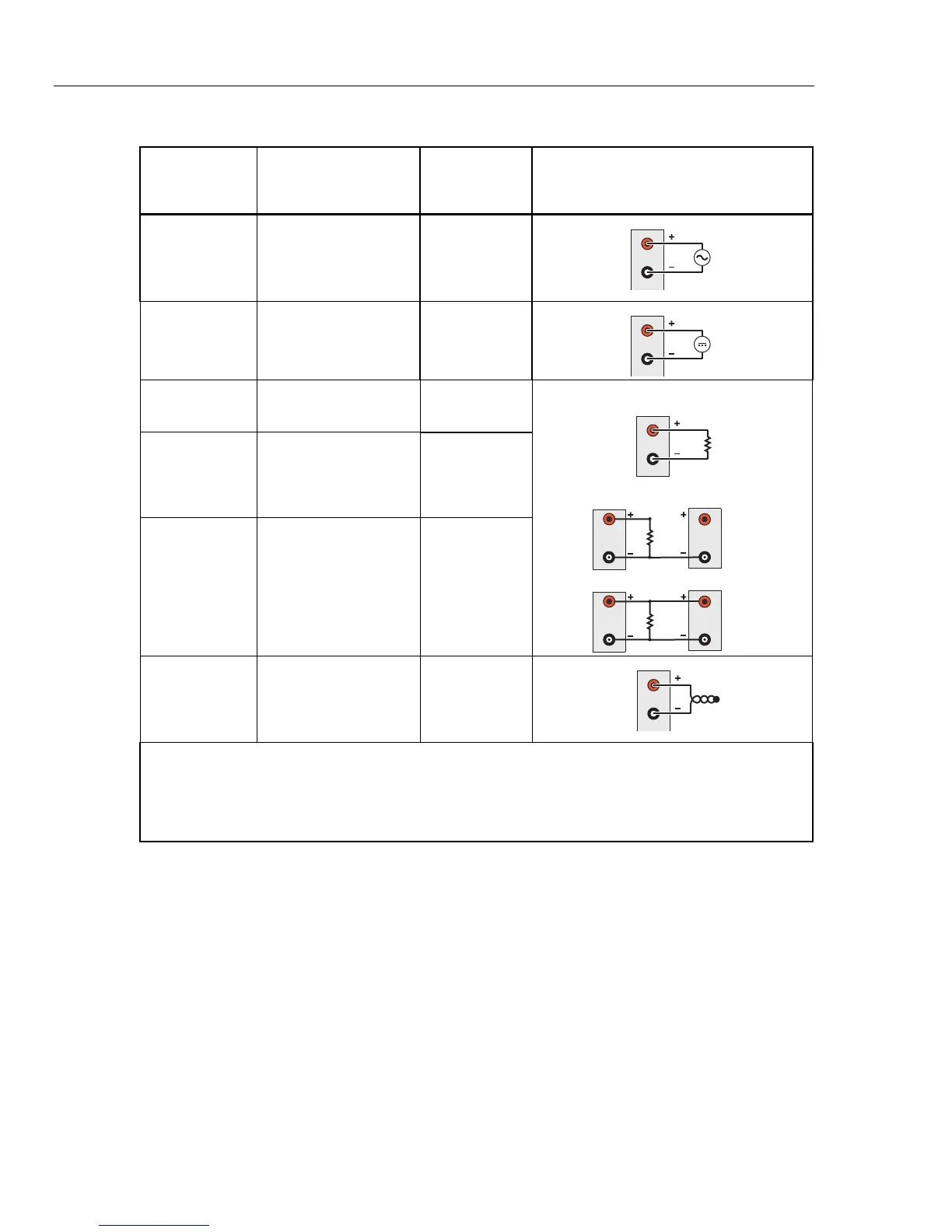
Table 3-1. Types of Inputs
Type of Input Range and Types
Channel
Configuration
Reference
Wiring Polarity
DC Voltage Range: 0 V to 50 V Page 3-19
H
L
V
DC Current
[1]
Range: 0 mA to 100 mA Page 3-19
H
L
V
Resistance (Ω)
2-Wire or 4-Wire
[3]
Range: 0 Ω to 100 MΩ
Page 3-20
H
L
R
2-Wire
H
Source
Sense
L
R
4-Wire
H
L
H
Source
Sense
L
R
3-Wire
H
L
Platinum
Resistance
Thermometer
(PRT)
2-Wire, 3-Wire or 4-Wire
Types: ITS90, CVD,
PT385, PT392
Page 3-23
Thermistor
2-Wire or 4-Wire
Types: R(T)
[2]
, 2.252
kΩ, 5 kΩ, 10 kΩ
Page 3-22
Thermocouple
Types: B, C, D, E, G, J,
K, L, M, N, R, S, T, U,
W, POLY
[2]
Page 3-21
H
L
Note
[1] − Each Input Module has two terminal sets (mA 21 and mA 22) that are dedicated to current measurements.
[2] – Custom characterized.
[3] − 100 M
Ω is for Ch001 only. Other analog channels are 10 MΩ Max.
Input Wiring Instructions
Use the procedure below and refer to Figure 3-1 for instructions on how to wire a 2-wire,
3-wire, or 4-wire input to the Input Module.
Warning
To prevent possible electrical shock, fire, or personal injury,
read the Wiring Safety and Considerations section on page 3-5.
1. Power off the Product with the main power switch.