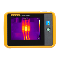
Camera Overview
Camera Display Screen
2
2-9
Table 2-2. Display Screen – Descriptions (cont.)
Item Description
N
Center box with temperatures – Center 50 by 50 pixel box with the
maximum, average, and minimum temperatures in the box (when
enabled).
O
Hot cursor temperature – Temperature and location of the hottest
temperature in the image; always in red (when enabled).
P
Cold cursor temperature – Temperature and location of the coldest
temperature in the image; always in blue (when enabled).
Q
Analysis point – Temperature of marker point in the image. You can
add up to three marker points (when enabled).
R
Analysis area – Min., avg., and max. temperatures of the marker area
in the image. You can add up to three marker areas (when enabled).
S
Picture-in-picture (PIP) – The fused, or blended, infrared/visible light
image appears in the center quarter of the display screen and the
visible light image appears in the rest of the display screen (when
enabled).
T
IR Fusion blend level dialog box – Used to change the IR Fusion
blend level from full infrared (IR) to full visible light (VL) or some
combination in between (Only TiR2, TiR3, TiR4, Ti45, Ti50, Ti55 IR
Fusion models). Disabled when using optional 10 and 54-mm lenses.