8
OUTPUT SYSTEM INSTALLATION
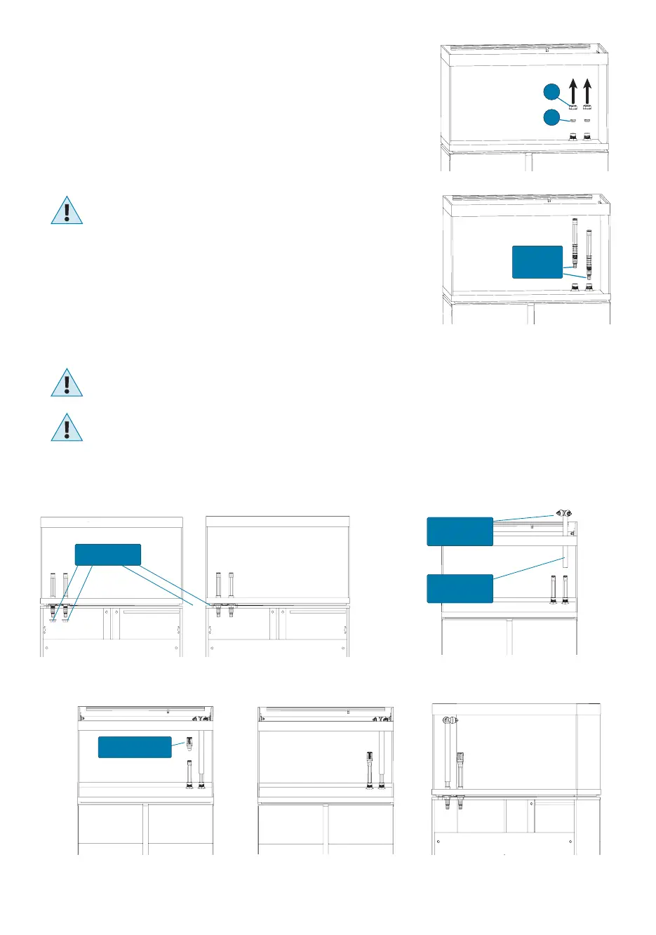
1. Manually unscrew plug (P) and remove plug (Q) from opening (O) (Pict. 1).
IMPORTANT: keep plugs (P) and (Q) for any future use.
2. Slip connector stem (A) fully through opening (O) until it stops (Pict. 2).
3. Open the cabinet. Screw and tighten the ring nut (R) onto the bottom end of stem (A) (Pict. 3).
4. Insert the output nozzle (N) into one end of output stem (B).
5. Insert output stem (B) onto connector stem (A) (Pict. 4).
6. Adjust the height of output nozzles according to your requirement by sliding outlet stem (B)
along connector stem (A).
7. The output nozzles (N) can be easily rotated to divert the water ow where desired.
Direct water jets so as not to let water overow from the tank.
Avoid directing the water jets towards the LED Strip Lights.
INTAKE SYSTEM INSTALLATION
1. Manually unscrew plug (P) and remove plug (Q) from opening (I) (Pict. 1).
IMPORTANT: keep plugs (P) and (Q) for any future use.
2. Slip the second connector stem (A) fully through opening (I) until it stops (Pict. 2).
3. Open the cabinet. Screw and tighten the ring nut (R) onto the bottom end of
the second stem (A) (Pict. 3).
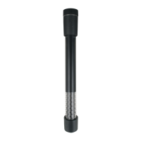
4. Insert the intake strainer (S) onto connector stem (A) (Pict. 5). The assembly end result
is shown on Pict. 6 and Pict. 7.
The height of the intake strainer is high enough to suit most standard aquarium decorations. When decorating the aquarium,
ensure it remains at least 2” (5 cm) from the gravel bottom at all times to prevent it from sucking gravel or sand and ensure that
no decorations block the passage of water. Ornaments and rocks should be positioned while the aquarium is still dry.
CAUTION!: Never force Connector Stems (A) sideways, as this may damage the Intake/Output systems and the glass tank.
In the event a dierent ltration system is used, which does not require the Intake/Output systems supplied with this unit
(e.g. an internal lter), restore the initial conditions by removing the 2 connector stems (A) and closing openings (O) and (I)
with plugs (P) and (Q). Plug (Q) ensures a watertight seal and has to be inserted into its seat by pressing it. Plug (P) is designed
to protect plug (Q) and ensure that plug (Q) remains in its seat properly. Screw plug (P) by hand only until it will no longer go
without forcing it. DO NOT USE ANY TOOLS, AS DOING SO MAY DAMAGE THE UNIT.
Connector
Stems (A)
Pict. 2
Pict. 1
Ring Nuts (R)
Pict. 3 Pict. 4
Pict. 5 Pict. 6 Pict. 7
Output
Nozzles (N)
Output
Stem (B)
Intake Strainer (S)
P
Q