5
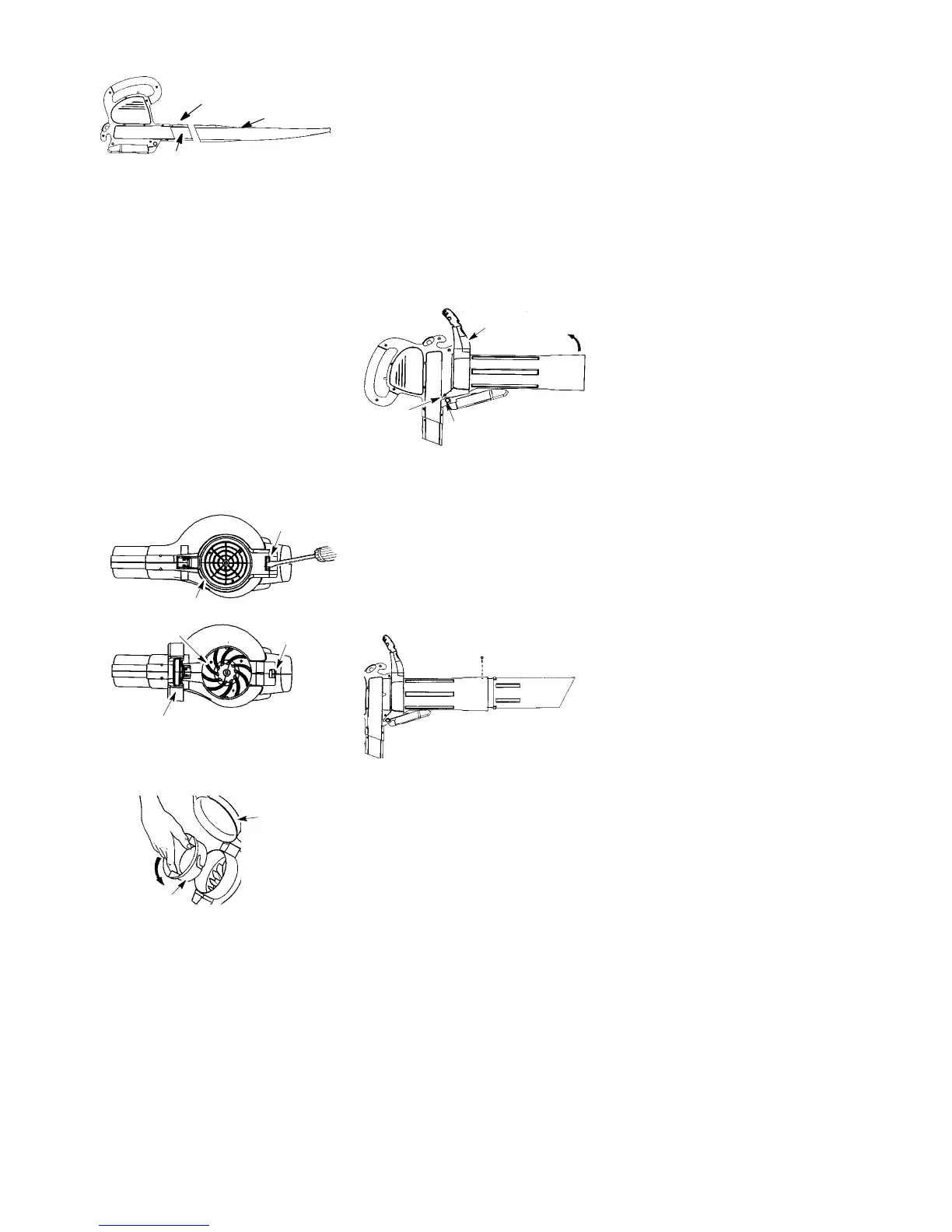
3. To remove the blower tube, press the
tube release button while pulling on
tube.
Blower Tube
Tube Release Button
Blower outlet
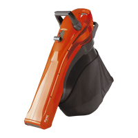
Vacuum Assembly
NOTE: Assembly instructions for using
your unit as a blower are explained in
the previous s ection.
If you have already assembl ed your uni t
for use as a blower, remove the blower
tube.
Remove the inlet restrictor
An inlet restrictor is used when using
your unit as a blower. Thi s r estrictor is
not used during vacuum use and must
be remove d dur i ng assem bly for vacu-
um use.
NOTE: Be sure to keep the inlet re-
strictor for using y our unit as a blower.
1. Ensure unit is stopped and t he mains
el ectricity supply is disconn e cted.
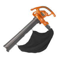
2. Open the inlet cove r by inserting the
tip of a screwdriver intothe latc h a rea
on the blower unit. Gently tilt hand le
of screwdriver toward the front of the
unit to release the latch while pulling
up on the vacuum inlet cov er with
your other hand.
Vacuum Inlet Cover (closed)
Latch Area
Bottom view
of unit
Vacuum Inlet Cover (opened)
Latch Area
Impeller
3. T urn the inlet rest rictor count erclock-
wise and remove it from the uni t. Do
not cl ose the inlet door. You will next
attach t he vacuum tubes.
Inlet
Restrictor
Vacuum
Inlet Cover
Attaching the vacuum tubes
There are 2 vacuum tubes, an uppe r
tube and a lower tube. The upper tube
has a vacuum as sist handle attached
to one end and is cut straight on both
ends. The upper tube attaches to the
blower unit. The lower tube has an
angled end that you point toward the
ground during vacuum use. The lower
tube attaches to the upper tube.
1. Ensure uni t is stopped and the mains
electr i cit y supply is disconnected.
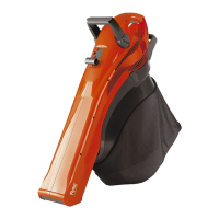
2. While holding inl et cover open, place
th e hooks of t he vacuum assisthandle
on the retaini ng posts of the uni t.
3. Raise the tube unti l it is secured to the
blower unit by the orange inlet cover
latch.
Retaining Post
Vacuum Assist Handle
Upper
acuum Tube
Hook
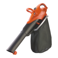
4. To attach the lower vacuum tube to
theup per vacuum tube,first align the
arrows on thetwo tubes. Then, press
the two tubes together until the lower
tube is securely seated in the upper
tube (about 7,6 cm). When vacuum
tubes are fitted together, locate the
label on the lower portion of the up-
per tube. Permanently assemble the
two tubes together with the s upplied
screw.
Align arrows on upper
and lower tubes
Upper
Tube
Lower
Tube
Screw
Collection Bag Assembly
1. Open the zipper on the collection
bag and insert the elbow tube.
2. Push the small end of the elbow tube
thro ugh the smallopening in theb ag.
NOTE: Make sure edge of the small
opening is flush against the flared area
of the elbow tube and the hole for the
tube release button is on top.