FS8 Co-Pilot™ user guide 6 FMA Direct
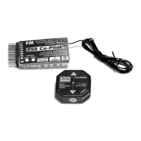
Parts list
¨ FS8 Co-Pilot™ ¨ Ribbon cable
¨ Pitch/Roll Sensor ¨ Velcro®
¨ Button and LED Module with cable and nameplate
Ribbon cable Velcro®
Button/LED Module FS8 Co-Pilot™
and Nameplate Pitch/Roll Sensor
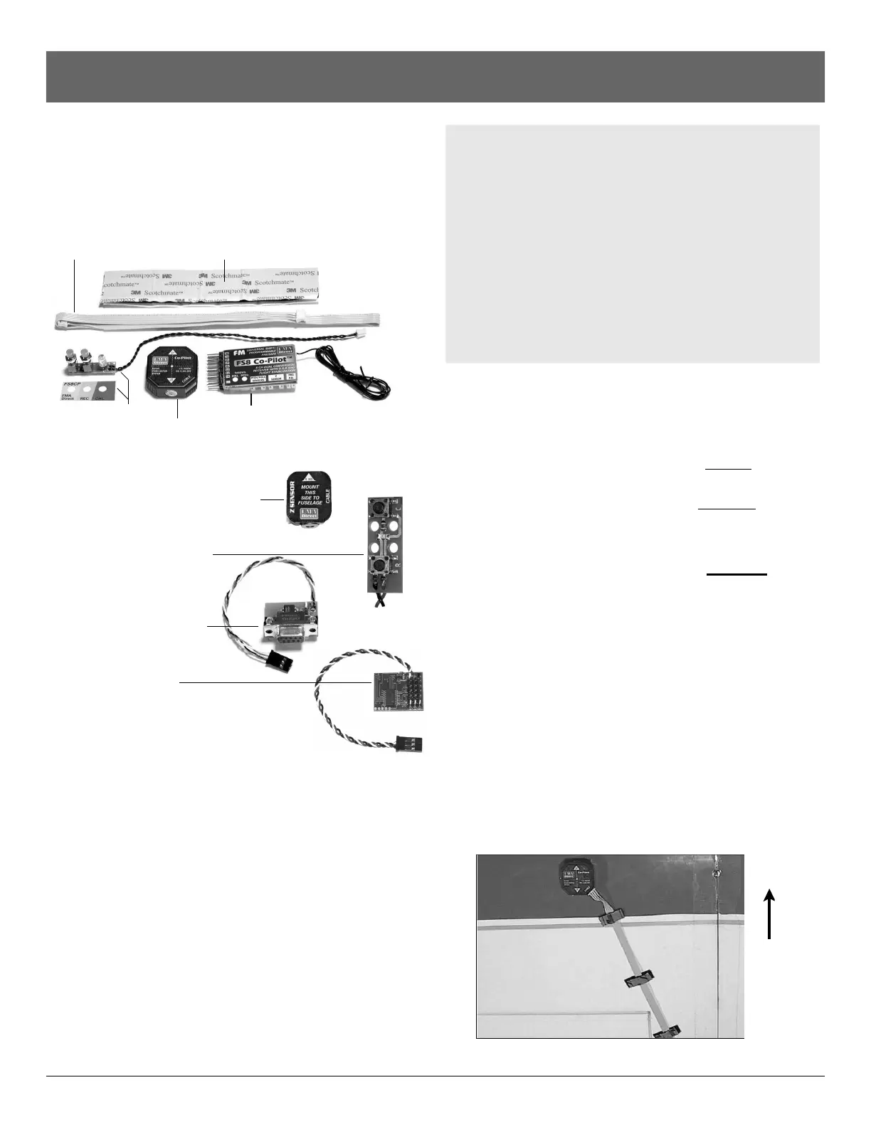
Optional components
¨ Vertical Sensor with ribbon cable
(Part no. FS8ZS)
¨ Low Profile Button/LED
Module for helicopters
(Part no. FS8HS1)
¨ Serial Interface Module
(Part no. FSIM1)
¨ FS Flight Recorder
(Part no. FSFR1)
Other items you may need
n Elevon Mixer (Part no. MX80). Use an on-board elevon
mixer for aircraft with elevons (such as flying wings), when
your radio control transmitter doesn’t provide elevon mixing.
n 12" (30cm) flat ribbon cable (Part no. 2MMFRC4P2X12)
18" (46cm) flat ribbon cable (Part no. 2MMFRC4P2X18)
24" (61cm) flat ribbon cable (Part no. 2MMFRC4P2X24)
40" (102cm) flat ribbon cable (Part no. 2MMFRC4P2X40)
l
Longer cables enable the Co-Pilot™ Sensor to be positioned
properly on engine-powered conventional aircraft having
large wingspans (see “Installing Co-Pilot™” for details).
l Shorter cables reduce weight on smaller aircraft.
Please measure to determine the correct ribbon cable
length for your aircraft!
n Advanced Servo Buffer (Part no. 605SB). Strongly recom-
mended for aircraft with long servo extensions and/or gasoline
engines. Works with analog and digital servos. See page 10
for more information.
Before you start
Failsafe and light stabilization work with, and require, a
completely installed and correctly operating aircraft radio
control system: transmitter, FS8 Co-Pilot™, battery pack
and servos. (An airplane with elevons may also need an
on-board mixer, if mixing isn’t provided in the transmitter.)
Before you work with failsafe settings and flight stabiliza-
tion, install and set up your entire radio system. Be abso-
lutely certain the radio system operates correctly—and
moves the control surfaces in the proper directions—be-
fore you get into FS8 Co-Pilot™ set up procedures.
Finally, read and understand the safety precautions on
page 5.
Install
Mount the Roll/Pitch Sensor
n If you are installing FS8 Co-Pilot™ on an airplane, go to
“Mount the Pitch/Roll Sensor on an airplane.”
n If you are installing FS8 Co-Pilot™ on a helicopter, go to
“Mount the Pitch/Roll Sensor on a helicopter.”
Mount the Pitch/Roll Sensor on an airplane
1. Locate a mounting spot for the Pitch/Roll Sensor, following
these guidelines:
n Pitch/Roll Sensor should be level during flight (a slight tilt
caused by mounting the sensor on a wing with dihedral is
acceptable).
n The Pitch/Roll Sensor should have a clear view of the hori-
zon on all sides.
n The Pitch/Roll Sensor must be away from muffler and ex-
haust spray (exhaust spray will cloud the sensor’s infrared
windows and degrade flight stabilization).
n On a high wing airplane, mount the sensor on top of the
wing about halfway between root and tip ribs, at about
maximum airfoil thickness, on the side away from the ex-
haust.
continued
Front of
airplane
 Loading...