Doc No: OMM50000903
Rev: B Page 49 of 65
Subject to contractual terms and conditions to the contrary, this document and all the information contained herein are the confidential and exclusive
property of FMC Technologies, and may not be reproduced, disclosed, or made public in any manner prior to express written authorization by FMC.
6. NOTE: Connecting rods and caps are
matched sets and must always be
reassembled with their original mate
and in the same orientation. Note the
numbered codes stamped on each
half of the connecting rod assemblies
and make certain they are installed as
matched set and in the same
orientation when re-assembling the
pump.
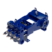
7. The L series pumps are configured as industrial pumps with pinion shafts for
internal gear reduction or as Horizontal Drill (HD) or High Volume (HV) pumps
that may have direct crankshaft driven design (no pinion shaft) with provision for
direct hydraulic motor mounting. If the pump is a direct crankshaft drive (no
separate pinion shaft) configuration, then skip to step 10.
8. For industrial pumps and HD pumps
with pinion shaft remove the hex
head cap screws (28),the left and
right pinion housings (17 and 18),
and shims (21) from the power
frame. The gaskets (20) may adhere
to the power frame surface and can
be left in place if they are not
damaged. Count and record the
number of shims on each side to
facilitate assembly. It may be
necessary to tap on the housings
with a rubber mallet to free the shims
from the pump frame. NOTE: The oil
seal (19), and on some models, the
bearing cup (25) will remain attached
to the pinion housing.
9. The pinion shaft (3) with bearings may then be removed from the drive side by
using a brass rod (or other soft material) and mallet to drive the shaft out. The
L16 pump will allow removal without the use of a mallet.
10. Remove the piston rod seals by referring to Section 10.4.1, “Replacing Piston Rod
Oil Seals”, for instructions.
11. Push the connecting rod (4) and crosshead assemblies (7) as far forward into the
power frame as possible to provide clearance for the crankshaft. The connecting
rod bolts should be removed completely to provide additional clearance when
removing the crankshaft and to reduce the possibility of damage to the crankshaft
journals.
Installation Tip: Mark the bearing housings and power frame for installation in the
original position.