Issue/Rev. 0.5 (6/11)
MN01029 • Page 3
Suggested Tools and Fixtures
In addition to ordinary hand tools, the following tools and
equipment will facilitate work on the meter.
• Feelergauges,leaf-type(seeTable1).
• Emerycloth.
• Woodblockorequivalent(seeFigure1).
Table 1 — Feeler Gauge Sizes
Part No.
1
Thickness Part No.
1
Thickness
515252-001 .0015" 515252-011 .011"
515252-002 .002" 515252-012 .012"
515252-003 .003" 515252-013 .013"
515252-004 .004" 515252-014 .014"
515252-005 .005" 515252-015 .015"
515252-006 .006" 515252-016 .016"
515252-007 .007" 515252-017 .017"
515252-008 .008" 515252-018 .018"
515252-009 .009" 515252-019 .019"
515252-010 .010" 515252-020 .020"
• Spiders
2
(Figure 2).
• CamSettingBushing
2
(for T-11 and I-75 Meters only)
- 552469-001, Figure 1A.
• CamSettingFixture
2
(for T-11 and I-75 Meters only)
- 552469-002, Figure 1A.
Disassembly of Model T-11 and I-75 Meters
Removing Rotor Assembly From Housing
1. Remove all accessories from top of meter.
•Thecalibratordoesnothavetoberemovedunless
jackshaft and gear, pinion gear, or packing gland
have to be replaced.
2. Remove meter housing cover, Figure 3.
•Slotsareprovidedaroundtheperimeterofthecover
to assist in prying the cover from the housing.
•Whenreplacingcover, turnadjustingscrewin
bottom of housing to the extreme clockwise
position.Thiswillplacetherotorassemblyon
thebottomofthehousingandallowthecover
to be firmly secured to the housing. If rotor
assemblyisnotbottomed,itispossibletodam-
agethecoverwhenitistightenedtothehousing.
Section 1 – General Information and Description (continued)
•Beforereplacingcover,applyathinlayerofseal-
ant (Master Gasket by Loctite is recommended)
aroundtheperimeterofthecovertoformaseal
betweenthehousingandthecover.Ifasealant
isnotused,uidmayleakoutofthecover.
NOTE:MeterswithO-RingsDONOTrequirea
Master Gasket
•Atreassembly,caremustbetakenthatthejack-
shaft gear, Figure 3, and rotor gear, Figure 4,
are properly meshed when the cover is
assembled to the meter body.
This is accomplished by slowly rotating the
calibrator output drive shaft as the cover is
loweredontothemeterhousinguntiltherotor
andjackshaftgearsmesh.
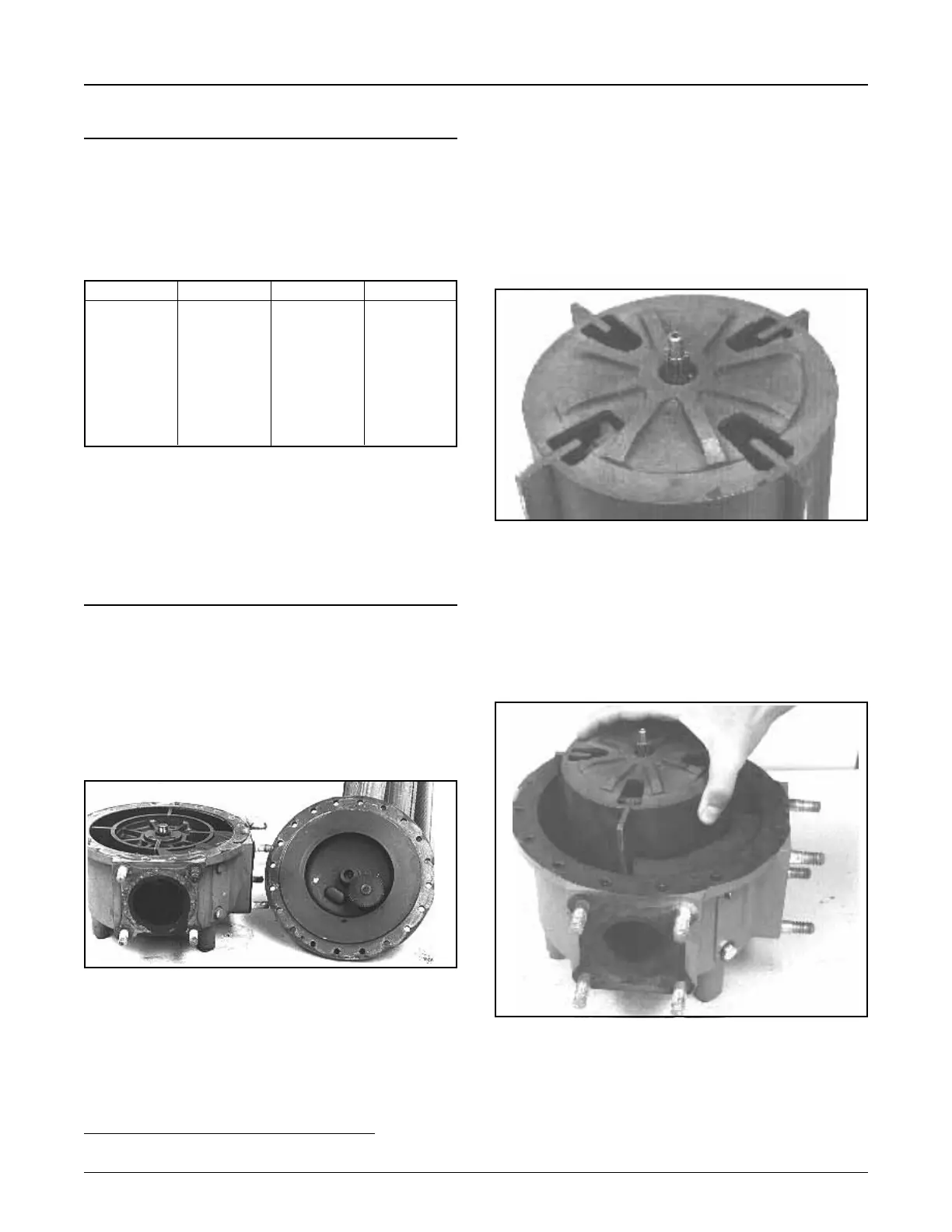
3. Remove rotor assembly, Figure 5, and clean rotor
and housing interior.
Figure 5
Figure 4
2 Available through Smith Parts Operation. Reference Form No. P1205.
•Liftstraightuptopreventdamagetotherotorblades.
•Ifthemeterhasbeeninserviceoncrudeoilorany
other viscous liquid, a solvent should be used to
dissolve the residue. Do not use water.
Figure 3