Page 4 • MN01029 Issue/Rev. 0.5 (6/11)
4. Turn rotor upside down and place on a wooden block
or equivalent.
•Thewoodenblockormetalplatemusthaveaclear-
ance hole in the center for the rotor shaft and high
enough to allow shaft to clear the table. Refer to
Figure 1, Page 2 for recommended block dimen-
sions.
5. The block, Figure 5, can be separated from the hous-
ing by removing the two block retaining bolts in the
side of the housing.
•When replacing the block, a sealant must be
appliedtothetwoblockretainingbolts(Master
Gasket by Loctite is recommended).This will
preventleakage.
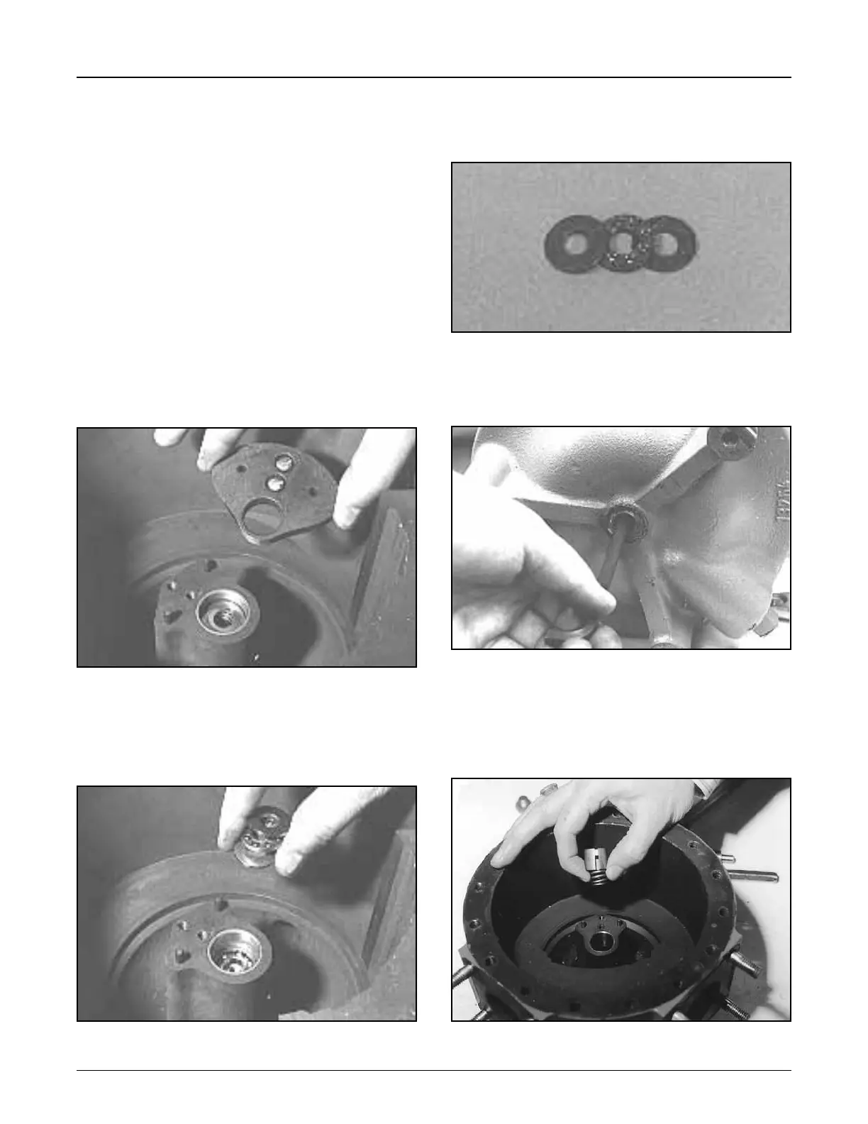
Removing Cam and Adjusting Mechanism
1. With rotor assembly removed, unscrew hold-down
screws and lift cam straight up from housing center
hub, Figure 6.
•Notelocatingpinsoncenterhub.
•RefertoPages16and17forinformationoncam
replacement.
2. Liftthrustbearingandrotorbearingfromhub,Figure7.
Section 1 – General Information and Description (continued)
•Whenreplacingthethrustbearing,indentside
ofthrustbearingplatesmustfaceoutwardfrom
retainerandballs,Figure8.
3. Remove plug from bottom of housing and use a 1/4"
Allen wrench to remove the adjusting screw, Figure 9.
•Turnscrewcounterclockwisetoremove.
4. Withadjustingscrewremoved,theadjusting collar
and rotor spring, Figure 10, can be lifted from the
housing.
•Whenreplacingspringandcollar,slotincollar
mustlineupwithkeypininhub,Figure10.
Figure 6
Figure 7
Figure 8
Figure 9
Figure 10