Issue/Rev. 0.5 (6/11)
MN01029 • Page 5
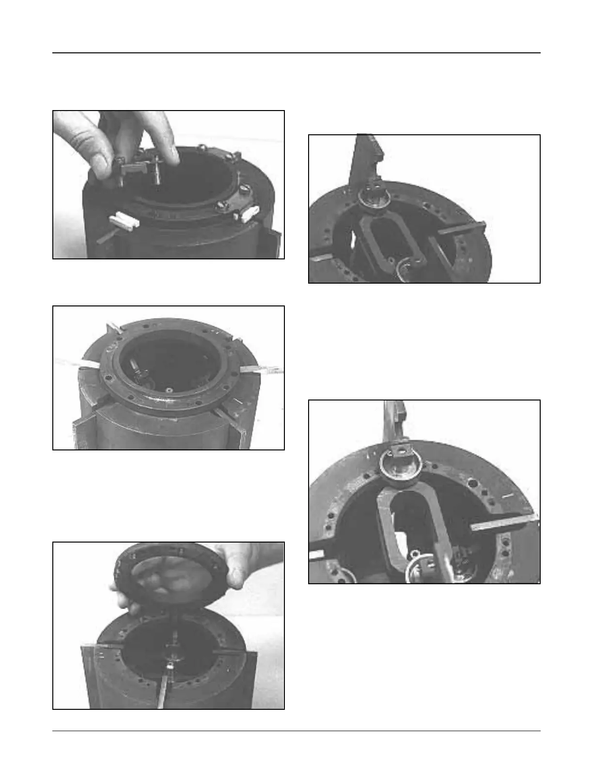
Rotor Disassembly
1. Remove clamps and blade blocks, Figure 11, from
rotor assembly.
2. Using two screwdrivers, pry rotor cover off rotor body,
Figure 12.
•Slotsareprovidedintherotorcovertoacceptthe
screwdriverblades.Withscrewdriversinslots,pry
upward uniformly. Do not pry downward with
screwdrivers, as damage could occur to the
bottom edge of the rotor body.
•Notelocatingpinsinrotorcover,Figure13.
Section 1 – General Information and Description (continued)
Figure 11
Figure 12
3. The blades are matched to their own slots during
manufacturing. Therefore, before removing blades
from the rotor, the blades and rotor slots must be
matched-marked to eliminate the possibility of install-
ing the blades in the wrong slots or 180° out of position.
• Figure 14 shows one method of marking blades
and rotor. Using a marker, make identical number of
marks on the blade yoke and on an area of the rotor
next to the blade slot. It is unnecessary to mark the
opposite blade paddle for obvious reasons.
•Donotmarkoutsideedgeofrotor.
4. The lower blade assembly can now be removed,
Figure 15.
•Because of the position of the rollers, it will be
necessary to maneuver the blade assembly out of
the rotor.
•Handle blade carefully so that the edges of the
blades are not damaged.
5. Place identification marks on the upper blade yoke
and rotor, Figure 15, and remove from rotor.
•Usedifferentsetofmarksthanusedonlowerblade.
Figure 13
Figure 14
Figure 15