page29
AMA
page27page23page21page19
step 10
page15
step 8
page16
step 8
page13
step 7
page14
step 7
page6page5
step 3
page3
step 1
Read the E NTIR E ins truc tion m anua l to bec ome f amil iar wi th the f eatu res o f the pr oduc t WARNING :
operatin g. Failu re to ope rate the p roduc t correc tly can r esult i n damage t o the pro duct, pe rsona l before
property a nd caus e serio us inju ry.
This is a sop histi cated h obby p roduc t and NOT a t oy. It mus t be ope rated w ith ca ution a nd comm on sen se
and enquires som e basic mecha nical abi lity. Failur e to operate th is Product in a sa fe and respo nsible man ner
could re sult in inj ury or dama ge to th e pro duct o r othe r pro pert y. This p rodu ct is n ot int ende d for u se by
children w ithou t direc t adult s uperv ision .
This manu al cont ains i nstru ction s for sa fety, op erat ion and m aint enanc e. It is e ssent ial to r ead and f ollo w
all the in stru ctio ns and w arni ngs in m anua l, pri or to a ssem bly, se tup or u se, in o rder t o oper ate co rrec tly
and avoid d amage o r seri ous inj ury.
!
Safety Pr ecaut ions an d Warni ngs
page2
As the use r of thi s prod uct, y ou are s olel y resp onsi ble fo r oper atin g in a man ner th at doe s not en dang er
yoursel f and o thers or res ult in d amag e to the p rodu ct or th e prop erty o f othe rs. Th is mod el is co ntro lled
by a radio s igna l subj ect to i nter fere nce fr om man y sour ces ou tside your c ontro l. This i nter feren ce can
cause mo menta ry los s of co ntrol s o it is ad visa ble to a lway s keep a sa fe dis tanc e in all dir ectio ns
around
your mod el, as t his ma rgin w ill he lp avo id col lisi ons or i njur y.
Age Recomm endat ion: No t for chi ldren u nder 14 years. Thi s is not a to y.
• Never oper ate you r model w ith low t ransm itter batterie s.
• from cars, t raffi c or peop le.Always ope rate yo ur mode l in an ope n area aw ay
• Avoid opera ting yo ur mode l in the st reet wh ere inj ury or da mage ca n occur.
• Never oper ate the m odel in t he stre et or in populate d areas f or any re ason.
• Caref ull y fol low t he di rect ion s and w arn ings for t his a nd an y opt iona l sup por t equ ipm ent ( char ger s,
recharge able ba ttery p acks, e tc.) yo u use.
• Keep all che mical s, smal l parts a nd anyt hing electric al out of t he reac h of chil dren.
• Moisture c auses d amage t o elect ronic s. Avoid w ater ex posur e to all eq uipme nt not sp ecifi cally d esign ed
• Never lick o r place a ny port ion of yo ur mode l in your m outh as i t could c ause se rious i njur y or even d eath.
and protec ted for t his pur pose.
page4page1
step 1
WARNIN G
page7
step 3step 2 step 3
page8 page9
step 5step 4
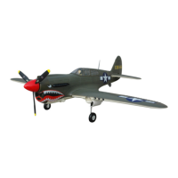
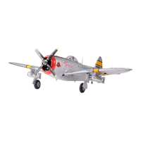
1 700MM P47
OPER ATING MA NUAL
page10
step 5
FMS K indly R emind er
Thank you for your great attention and
support to our company.
If there is any problem regarding the plane,
or any suggestion on our products, such as
manual, package, color scheme, even
structure, please feel free to contact
us at info@fmsmodel.com
page11
step 5
The con trol ho rns ins talla tion
Glue th e bomb ra ck
1. Lay the in s tored a ccess ories o ut.
Every con trol su rface s has its o wn
special l abele d acces sory pl astic b ag.
2. Take the ele vator a ccess ory bag o ut.
It has been l abele d eleva tor.
4. Make sur e the con trol su rface h orns ar e
facing in to the ri ght dir ectio n befor e
install ing for t he desi red mos t refle ction
without a ny bind ing.
5. Always m ake sur e that th e screw s are
grabbin g into th e back pl ates of t he
control h orns. I t is very i mport ant tha t
these par ts are ho lding t ight.
3. Instal l the ele vator c ontro l surfa ce
horns on th e botto m of the el evato r
surface w ith the s crews p rovid ed in the
small pla stic ba g.
The side of t he stab ilize r that co ntain s
the plast ic wash er face s up, mak e sure
to instal l the con trol ho rns on th e
opposit e side.
1
2
3
5
4
6. Verify th e compl eted el evato r horns
install ation .
: Do not disc ard the e xtra sc rews,Note
it will be pr eserv ed for th e futur e
model bui lding .
7. Repeat t he step 3 .4&5 fo r the ail erons
control h orn ins talla tion.
8. Repeat t he step 3 .4&5 fo r the fla ps
control h orn ins talla tion.
7.1
7.2
6
8.1
8.2
2. Put the Z-bend end of the linkage into
the desired servo control horn hol e.
It is a tight fit and should allow the linkage
to move just slightly within the hole to
avoid binding up.
1. Make sure i mplem ent the in s tored
rubber sec uring t ube on the c ontrol r od.
3. Snap the c levis i nto the s urfac e contr ol
horn.
4. Secure t he horn s with th e tube, m ake
sure do not s lide th e tube to t he horn
side too mu ch, or it w ill bin ding wi th
the horn.
Just make s ure it’ s secur ing eno ugh.
1
1. Pre read y appro priat e amoun t of glue
for the nex t step mo del bui lding .
2. Take the pre serve d eleva tor acc essor y
bag and sec ure the h orizo ntal st abili zer
with two ma chine s crews .
Make sure t he top si de of the s tabil izer
face up.( Screw : PM3.0 *50 3PC S)
3. Fix the dorsal foam fin to the fuselag e slot.
we recommended only apply glue on th e
underside of the fin.
1
2.1
2.2
3.1
3.2
4. Make sure align the slot o n the horizontal
stabilizer with the fu selage tail slo t.
5. Install th e vertica l stabili zer, Apply glu e
to the place whe re the vert ical stab ilizer
fitting tog ether wit h the horizo ntal
stabilize r and fusel age assem bly.
Use a brush or spa ckle to thor oughly
cover the notc h with a thin la yer of glue .
We recommend t o apply glu e to the
fuselage an d elevato r as well for a bet ter
bond.
Let dry off for at le ast 5 minut es.
Note: Do no t apply g lue on th e rudde r
side foam h inge an d fusel age tai l slot.
6. Insert t he vert ical st abili zer int o the
assembl y sligh tly.
7. Make sur e the rud der sid e foam hi nge
has inser ted int o the slo t in the pr ocess
of stabil izer mo untin g.
To protect th e foam hi nge fro m any
damage or t wisti ng we rec ommen ded
you to clea n the fus elage t ail slo t first
for the smo othly h inge in serti ng.
5.1
5.2
6
7
4
8. Make sur e there i s no gap in b etwee n
the rudde r and the s tabil izer.
9. Install th e rudder co ntrol hor n the same
with the eleva tor cont rol horn, m ake sure
the horn be inst alled in pr oper dire ction.
10. Apply a thin coat o f glue on the ele vator
underside fo am hinge it wil l great help ful
for the hinge dur ability.
Do not apply exce ssive glue i n this area
which might pre vent the sur face from
moving freel y.
9.1
8
9.2
10
1. Make sur e to inst all the o il tank r acks on
their des ignat ed side s.
2. Rack mou nted th e wrong w ay roun d.
Note that t he rear p art of th e rack ar e
asymmet rical a nd the ra ck will n ot fit
into the no tch if yo u try to mo unt it as
shown in th e pictu re.
3. This is how the pla te should be mo unted.
4. Remove the rack and gl ue them back into
place.
1
2
3
4.1
4.2
2. Plug the leads fro m the main wing to the
Multiple Conne ctor Part 1 with th e yellow
signal at the chann el label side.
This step has been fact ory comple ted,
you may repeat it when yo u do the main
wing maintenan ce or repair.
3. There ar e two gla ss fibe r tubes i n
differe nt leng ths for t he main w ing
connect ion.
The short o ne on the l eadin g edge si de
the long on e on the tr ailin g edge si de.
1. Fit the wi ng fill er into p lace fi rst.
There are t wo fill ers in th e kit, on e for
each side .
Make sure t o insta ll the fi llers o n their
designa ted sid es.
1.1
1.2
1.3
2
3
4. Insert th e tubes i nto the ma in wing
sockets ti ll the wh ite mark i mpleme nt
in factory.
Do not push th em farth er than t hey will
go with litt le resi stance .
That would p ush the wi ng tubes i nto the
foam of the wi ng and pre vent th em from
fully inse rting i nto the op posite w ing hal f.
5. Remove the w ing tube, ap ply a thin co at
of glue to the fib erglass w ing tube fr om
the end to the fir st white ma rk.
Let dry off for at le ast 5 minut es.
Then insert it i nto place , it will hel p the
tubes grab in to the socke t more firm .
7. Mount th e main wi ng with t he tube s to
the fusel age slo t.
Make sure t he wing t ubes st raigh t
through t he hole s in bott om of the w ing
mount not ch.
6. Rise the c anopy b y holdi ng the ri bbon
on the rear o f the can opy.
4.1
4.2
6
7
5
8. Guide th e two ail eron se rvo cab les
through t he hole s in the bo ttom of t he
wing moun t notch , and gen tly pul l the
aileron s ervo ca bles fr om insi de of the
canopy si multa neous ly to avo id any
tanglin g of the se rvo cab les.
9. Mount the other wing panel to the tubes,
make sure put the tubes into the sockets
first, then push the wing into place slightl y.
10. Two wing p anels w ill per fectl y fit int o
the notch w ith no ga p revea l betwe en
the main wi ng root a nd the fu selag e.
11. Secure t he main w ing fro m the can opy
hatch usi ng the fo ur prov ided sc rews.
Two extra pi eces of t he are sp ares.
(Screw: 6 .0*80 4 PCS)
9
8
11.1
1. Fit the gu n set int o place t he firs t, it wil l
fitted pe rfect ly into p lace or y ou have t o
fit anoth er one wi th the ye llow ba nd
alignin g.
2. Remove t he gun se t and glu e it back
into plac e.
3. Glue the a ir spee d indic ator on to the
port side p re-no tched s lot.
4. Glue the a ir spee d indic ator in to the
pre-not ched sl ot in the d orsal f in.
4.1
4.2
3.1
3.2
1
2
Hook on t he link age rod
Insta ll th sta biliz er
Mount t he main w ing to th e fusel age
page12
step 6
Insta ll the sm all par t
1. Take the propeller back plate out , the one with a
hex hole in center. Place the in store d nuts into
the peripheral pre-no tched nuts hole on ba ck of
the plate.
2. Then fit the blade in plac e with the letter s ide
face up, use the shorter sc rew in stored wi th the
spinner to secure the bl ade in the blade ti p side
screw hole.
4. After the i nstal latio n of the bl ade mak e sure
there is no ga p betwe en the ba ck prop eller
holder pla te and th e prope ller ro ot, if no t,
you will hav e to chec k to make s ure the re is
nothing co me to obs truct t he full y insta llati on
of the blade , and the n tight en the sc rew
properly a gain.
Do the rest 3 pi eces bl ade the s ame.
5. Place the f ront pr opell er hold er plat e into
place as sho w.
3. Make sure ho lding t he nut int o place w hen we
tighten th e screw.
It will help a lo t when yo u doing th e screw
installa tion and s ave you ex tra tim e.
(Screws: P M3*20 4P CS)
1
2
3
4
5
The pro pelle r blade a ssemb ly
4
3
2
page30
AMA
page28
FMS Use r Manua l of 6A UBE C
page22
page24
Note: We recommend use the jumper cap to connect the two middle pins in four for
your safty flying.
Specification Of 6A UBEC:
1. Switch Mode
2. Output:5.0V/6A ,5.5V/6A or 6.0V/6A switchable(Changeable with a Silver jumper)
3. Input:6V-25V (2-6S Lipo, 5-18S NiMH/NiCd)
4. Output Current:Continuous Current 6A, Burst Current 10A
5. Size:45.0mm*23.0mm*10.0mm(Length*Width*Height)
6. Weight:18.0g
Features:
1. Adopting the USA CPU and decreasing the electromagnetic interference, to be
sure that receiver works well.
2. The working status of UBEC is shown by an indicator (LED). When UBEC works,
the Silver LED lights.
3. Battery polarity reversal protection (If the connection is wrong, the UBEC can
not work.)
How to Use the UBEC, please carefully look at the connections as follows :
1. Connecting UBEC with ESC OPTO, you just parallelly connect the input connector
of UBEC with the battery pack, and plug the output connector of the UBEC into
one of spare channels of the receiver.
2. Using ESC SBEC, you must remove the red wire of the signal wires of ESC
SBEC to receive r before conne cting with the U BEC.(the co nnection wit h ESC
SBEC is same as co nnection wit h the ESC OPTO)
Note: Because o f the weather a nd ground, pl ease connect t he UBEC at
least in a dis tance 5cm far away from the receiv er to avoid the
electromagne tic interfere nce.
Receiver
+
Battery Pack
_
UBEC
Brushless ESC
(BEC)
Remove the Red Wire
Red
Black
Receiver
+
Battery Pack
_
UBEC
Brushless ESC
(OPTO)
Color:Brown,Red,Orange
Red
Black
Extra pro pelle r nosie
or extra Vi brati on.
Reduced f light t ime or
aircraf t under power ed.
Control su rface doe s
not move, or is s low to
respond to co ntrol
inputs.
Control r evers ed.
Motor los es powe r.
Motor pow er puls es
then moto rlose s power.
LED on receiv er
flashes slo wly.
Damaged s pinne r, prope ller.
motor or mo tor mou nt.
Loose pro pelle r and spi nner
parts.
Propell or inst alled b ackwa rds.
Flight ba ttery c harge i s low.
Propell er inst alled b ackwa rd.
Flight ba ttery d amage d.
Control s urfac e, cont rol hor n,
linkage o r servo d amage , Wire
damaged o r conne ction s loose .
Channel s need be r evers ed
in the tran smitt er.
Damage to m otor, or b atter y.
Lose of pow er to air craft .
ESC uses de fault s oft Low
Voltage Cu toff( LVC).
Power los e to rece iver.
Aircraf t will no t
respond t o the
throttl e but res ponds
to other co ntrol s.
ESC is not ar med.
Throttl e chann el is rev ersed .
Lower thrott le stick and t hrottle
trim to lowest se ttings.
Reverse thro ttle chan nel on
transmitt er.
Replace d damag ed part s.
Tighten p arts fo r prope ller
adapter, p ropel ler and s pinne r.
Remove an d insta ll prop eller
correct ly.Com plete ly rech arge
Flight ba ttery.
Remove and in stall pr opelle r
correctl y. Replace fl ight bat tery
and obey flig ht batte ry
instruct ions.
Replace o r repai r damag ed
parts and a djust c ontro ls.
Do a check of c onnec tions f or
loose wir ing.
Do the Cont rol Dir ectio n Test
and adjus t contr ols
for aircr aft and t ransm itter.
Do a check of b atter ies,
transmi tter, re ceive r, ESC,
motor and w iring f or dama ge
(replac e as need ed).
Land airc raft im media tely an d
Recharg e fligh t batte ry.
Check con necti on from E SC to
receive r.
Check ser vos for d amage .
Check lin kages f or bind ing.
Possib le Caus e Soluti on
Proble m
Batte ry Sele ction a nd Inst allat ion.
1. We recom mend th e 22.2V 3 300mA h 25C Li- Po batt ery.
2. If using a nothe r batte ry, the ba ttery m ust be at l east a 22 .2V 330 0mAh 25 C batte ry.
3. Your b att ery s hou ld be a ppr oxi mat ely t he sa me ca pac ity , dim ens ion a nd wi ght a s the
22.2V 3300mAh 2 5C Li-Po bat tery to fit in the f uselage wi thout chan ging the cen ter of gravi ty
a large amo unt.
Trouble shooting
AMA
If you are no t alrea dy a memb er of the AM A, plea se join , The AMA is th e gover ning bo dy
of model av iatio n and mem bersh ip prov ided li abili ty insu ranc e cover age, pr otect s
modeler s’ righ ts and in teres ts and is r equir ed to fly a t most R/ C sites .
Academy o f Model A erona utics
5151 East M emori al Driv e
Muncie, I N 47302 -9252
Ph.(800 )435- 9262
Fax(765 )741- 0057
Or via the In terne t at: htt p//ww w.mode lairc raft .org
A model airc raft is a n on-hu man-c arryi ng airc raft ca pable o f susta ined A.G ENERA L:
flight in t he atmo spher e. It may n ot exce ed limi tatio ns of thi s code an d is inte nded
exclusi vely fo r sport , recre ation a nd/or c ompet ition .
All model fl ights m ust be co nduct ed in acc ordan ce with t his saf ety cod e and any
additio nal rul es spec ific to t he flyi ng site .
1. Model ai rcraf t will no t be flow n:
(a) In a care less or r eckle ss mann er.
(b) At a locat ion whe re mode l aircr aft act iviti es are pr ohibi ted.
2. Model ai rcraf t pilot s will:
(a) Yield th e right o f way to al l man car rying a ircra ft.
(b) See and a void al l aircr aft and a s potte r must be u sed whe n appro priat e.
(AMA Docum ent #54 0-D-S ee and Avo id Guid ance. )
(c) Not fly h igher t han app roxim ately 4 00 feet ab ove gro und level wit hin three (3) mil es
of an airpo rt, wit hout no tifyi ng the ai rport o perat or.
(d) Not int erfer e with op erati ons and t raffi c patter ns at any air port, he lipor t or seapl ane
base exce pt wher e there i s a mixed u se agre ement .
(e) Ensur e the air craft i s ident ified w ith the n ame and a ddres s or AMA numb er of
the owner o n the ins ide or af fixed t o the out side of t he mode l aircr aft.
(This doe s not app ly to mod el airc raft fl own ind oors) .
( f ) Not opera te airc raft wi th meta l-bla de prop eller s or with g aseou s boost s excep t for
helicop ters op erate d under t he prov ision s of AMA Docu ment #5 55.
(g ) Not oper ate mod el airc raft wh ile und er the in fluen ce of alc ohol or w hile us ing any
drug whic h could a dvers ely aff ect the p ilot’ s abili ty to saf ely con trol th e model .
(h ) Not oper ate mod el airc raft ca rryin g pyrot echni c devic es whic h explo de or bu rn,
or any devi ce whic h prope ls a proj ectil e or drop s any obj ect tha t creat es a haz ard
to person s or prop erty.
Academ y of Mode l Aeron autic s Natio nal Mod el Aircr aft Saf ety Cod e
Effect ive Jan uary 1, 2 011
Except ions:
◆ Free Flig ht fuse s or devi ces tha t burn pr oduci ng smok e and are s ecure ly atta ched t o
the model a ircra ft duri ng flig ht.
◆ Officia lly des ignat ed AMA Air Sho w Teams (AS T) are au thori zed to us e devic es and
practic es as def ined wi thin th e Team AMA Prog ram Doc ument ( AMA Docu ment #7 18).
3. Model ai rcraf t will no t be flow n in AMA sanc tione d event s, air sh ows or mo del
demonst ratio ns unle ss:
(a) The air craft , contr ol syst em and pi lot ski lls hav e succe ssful ly demo nstra ted all
maneuve rs inte nded or a ntici pated p rior to t he spec ific ev ent.
(b) An inexp erien ced pil ot is ass isted b y an expe rienc ed pil ot.
4. When and w here re quire d by rule , helme ts must b e prope rly wor n and fas tened .
They must b e OSHA, D OT, ANSI, SN ELL or NOC SAE app roved o r compl y with
compara ble sta ndard s.
B. RADIO CO NTROL ( RC)
1. All pilot s shall a void fl ying di rectl y over un prote cted pe ople, v essel s, veh icles o r
structu res and s hall av oid end anger ment of l ife and p roper ty of oth ers.
2. A successf ul radi o equip ment gr ound- range c heck in a ccor dance w ith man ufact urer’ s
recomme ndati ons wil l be comp leted b efore t he firs t fligh t of a new or r epair ed mode l
aircraf t.
3. RC model a ircra ft must u se the ra dio-c ontro l frequ encie s curre ntly al lowed b y the
Federal C ommun icati ons Com missi on (FCC ). Only i ndivi dual s prope rly lic ensed b y
the FCC are a uthor ized to o perat e equip ment on Am ateur B and fre quenc ies.
4. RC model a ircra ft will n ot oper ate wit hin thr ee (3) mi les of an y pre-e xisti ng flyi ng site
without a f reque ncy-m anage ment ag reeme nt (AMA Do cumen ts #922 -Testi ng for RF
Interfe rence ; #923- F reque ncy Man ageme nt Agree ment)
5. With the e xcept ion of ev ents fl own und er offi cial AMA Co mpeti tion Re gulat ions,
excludi ng take off and l andin g, no pow ered mo del may b e flown o utdoo rs clos er than
25 feet to an y indiv idual , excep t for the p ilot an d the pil ot's he lper( s) loca ted at th e
flight li ne.
6. Under no c ircum stanc es may a pi lot or ot her per son tou ch a mode l aircr aft in fl ight
while it is s till un der pow er, exce pt to div ert it fr om stri king an i ndivi dual.
This does n ot appl y to mode l aircr aft flo wn indo ors.
7. RC night f lying r equir es a ligh ting sy stem pr ovidi ng the pi lot wit h a clear v iew of th e
model’s a ttitu de and or ienta tion at a ll time s.
8. The pilo t of a RC mod el airc raft sh all:
(a) Maint ain con trol du ring th e entir e fligh t, main taini ng visu al cont act wit hout
enhance ment ot her tha n by corr ectiv e lense s presc ribed f or the pi lot.
(b) Fly usi ng the as sista nce of a ca mera or F irst- Perso n View (F PV) onl y in acco rdanc e
with the pr ocedu res out lined i n AMA Docum ent #55 0.
C. FREE FLI GHT
1. Must be at l east 10 0 feet do wnwin d of spec tator s and aut omobi le park ing whe n the
model air craft i s launc hed.
2. Launch a rea mus t be clea r of all in divid uals ex cept me chani cs, off icial s, and ot her fli ers.
3. An effect ive dev ice wil l be used t o extin guish a ny fuse o n the mod el airc raft af ter the
fuse has co mplet ed its fu nctio n.
page17
step 9
page18
step 9
1. ver with yo ur tran smitt er Bind your r ecei
the first , please re fer to your Transmitter
Manual an d read it t hroug hly for t he
safety op erati on.
Do not inst all the p ropel ler ass embly t o
the motor s haft wh ile tes ting th e contr ol
surface t o make sure th e motor doe s not
start une xpect edly an d cause p erson al
injury..
Make sure all the contr ol stic ks in neut ral
positions (fli ght cont rol, rudde r, elevato rs
and ailerons ) or to low po sitio ns(th rottl e,
throttl e trim) .
Fully cha rge the b atter y befor e armin g
the ESC.
All of the se rvo hav e been fa ctory s et in
neutral p ositi on .
Thread th e clevi s on the li nkage s rod of
the ailer ons to ma ke the co ntrol s urfac e
align wit h the tra iling e dge of th e win tip .
: Please se cure th e clevi s again , Note
when the ad justi ng proc ess com plete d.
2. Adjust th e flaps ’ fligh t posit ion, ma ke
sure the up p ositi on alig n with th e
trailin g edge of t he wing f iller.
3. Adjust t he rear l andin g gear di recti on
by trim the r udder c hanne l.
Make sure t he whee l align w ith the
fuselag e cente rline .
1.1
1.2
2
3
4. Adjust th e rudde r neutr al posi tion by
back and fo rth the l inkag e rod in th e
control c onnec tor, mak e sure to l ock
the contr ol rod by t ighte n the hex h ead
screw
The re will b e no rudd er trim u sedNote:
in this ste p.
It will kee p the uni form of d irect ion of
the tail wh eel and r udder.
5. Adjust t he elev ator by b ack and f orth
the linka ge rods o f the ele vator i n
canopy ha tch.
The two pie ces elevat ors Note : spl it
must be kee p in the sa me alti tude.
6. Cycle th e landi ng gear s evera l times ,
make sure t he land ing gea r perfo rm
well in eve ry cycl e and the t hree po int
gears mov e the sam e direc tions .
7. Test the motor make sure it is resp onsive
to the throttle input an d rotate the cloc k
wise from the tail view, or you ha ve to
reset the throttle .
4.1
4.2
5
6
7
Aileron
Landing Gea r
Flap
Receive r
Channel-1
Channel-2
Channel-3
Channel-4
Channel-5
Channel-6
Ch1
Elevator
Ch2
Throttle
Rudder
Ch3
Ch4
Ch5
Ch6
6. Diagra m for the r eceiv er conn ectio n.
The recomm ended v oltag e inpu t for the
receive r is 4.8V- 6V.
5. Diagram f or the se quenc er conn ectio n.
Ch5 B
Ch5 B
Ch5 C
Ch5
5
4. CH5.B fo r the rea r landi ng gear r etrac t.
2. Multip le Conn ector P art 2
1. Multip le Conn ector P art 1
3. Plug the P art 1 to th e part 2 pr operl y as
the pictu re show.
1
Ch5
Two ribbon cab les fro m
the wing pane l.
Ch6
Ch1
Ch5.B
4
2
3
Contr ol surf ace tes ting an d setti ng
page20
step 10
Insta ll the pr opell er
1. Disarm t he ESC fi rst, th en turn o ff the
transmi tter.
2. Keyed the p ropel ler ass embly t o the mot or
shaft, mak e sure fi t the ass embly i nto the h ex
stage on the s haft, i t will he lp to hol d the
assembly i n fixed p ositi on when t he engi ne
contact.
1
2.1
2.2
2.3
The sugge sted th rows fo r the FMS P 47 are as f ollow s:
High rat e Low rate
Elevato r - 40mm/ 1.6in u p an down 2 4mm/0 .9in up a nd down
Rudder - 25 mm/0. 98in le ft and ri ght 21m m/0.8 in left a nd righ t
Aileron s - 28mm/ 1.1in u p and dow n 17mm/ 0.7in u p and dow n
Flap - Mid 22 mm/0. 9in
Full 45mm /1.8i n
Main spe cifi cati on an d sp are p arts
Item#
Descri ption
SH101-S ilver F usela ge
SH102-S ilver M ain win g set (2 PC S)
SH103-S ilver R udder
SH104-S ilver E levat or
SH105 Cow l
SH106-S ilver S pinne r ( 2 Hub hal ves and a s pinne r)
SH107-S ilver C anopy ( One PC pl astic c anopy )
SH108-S ilver C anopy ( One PC fo am cano py with out the s cale pl astic c ontro l desk)
SH109-S ilver B omb (2 PC S)
SH201 Bru shles s motor ( 5060- KV300 )
SH202 ESC ( 85A ESC wi th 5A SBEC & 6 A UBEC)
SH203 9g Se rvo
SH204 25g M etal se rvo
SH205 E-R etrac t (One PC f or main l andin g gear)
SH206 E-R etrac t (One PC f or rear l andin g gear)
SH207-S ilver M ain lan ding ge ar set (A pa ir with c hock ab sorpt ion fun ctio n)
SH208-S ilver E -Retr act sys tem (Fo r main la nding g ear,
with two re tract s and mai n landi ng gear i nstal led)
SH209-S ilver E -Retr act sys tem (Fo r rear la nding g ear,
with one re tract a nd rear l andin g gear in stall ed)
SH301 Pro pelle r (4 PCS bl ades)
SH302 Lin kage ro d (All of t he cont rol sur face li nkage s with cl evis a nd secu ring tu be
pre insta lled)
SH303 Mot or moun t
SH304-S ilver S ticke rs (A piec e of inta ct stic ker she et)
SH305-S ilver M ain lan ding ge ar door ( A pair of ma in land ing ge ar inne r fairi ng door
with the in stall ation b ase)
SH306-S ilver R ear lan ding ge ar door ( Rear la nding g ear bo x with tw o pcs doo r halve s)
SH307 Scr ews set
SH308 Mot or boar d
SH309 Mot or shaf t
SH310 Pla stic sc ale coc kpit ( A set of p lasti c cockp it dash board )
SH311 Mult iple co nnect or part 1 ( From th e wing pa nels)
SH312 Mul tiple c onnec tor par t 2 (For pl uggin g to rece iver)
Spare part list for silver scheme
7. Attach t he rece iver to t he cock pit hat ch
using the h ook and l oop str aps.
The minim um dist ance be tween t he
UBEC and re ceive r is 50mm / 2in.
8. Try to fix t he lead s from th e rear pa rts
of the fuse lage to a void ta nglin g with
the servo a rms.
9. Tuck the e xtra wi re mess i nto the p it in
the hatch f or a neat ly look ing of th e
canopy ha tch.
10. Battery hatch in front of the canopy hatch.
Do not arm the ESC if the instruction Note :
manual do not required you perform it.
The wir e conne ction
7
8
9
10
Range Ch eck Your Ra dio Sys tem
your
After final asse mbly, range che ck the radio s ystem with the FMS P47. Refer
to
specific
transmitter instruction manual for range test information .
12. Find a safe and o pen ar ea.
2.Charge fl ight batter y
.
3.Read thi s instructio n manual thoro ughly
.
4.Fully as semble mode l
.
5.Insta ll the flight battery in th e aircraft (on ce it has been ful ly charged )
.
6.Bind ai rcraft to your t ransmitter
.
7.Make su re linkages m ove freely
.
9.Perform the Control Direction Test with the transmitter.
10. Adj ust light controls and tran smitter.
11. Perform a radio system Ran ge Check.
1. Remove a nd insp ect con tents .
8. Make sure the rubb er ring h as been p roper ly slid e on the cl evis .
First Fl ight Pr epara tion
Take off and landing tips
Please r ead the f ollow ing ins truct ions an d fully u nders tand it .
3. Child ren un der th e age of 1 2 shou ld have a n adul t guid e. Nev er rec ommen d for th e chil dren
under th e age of 1 4.
4. Never le ave the c harge r in wet co nditi ons.
5. The P 47 is m ade f rom PA a nd pol yth ene w hic h are t ind er. Wh en it m eet s the h eat ,
tran sfig ura tion can e asil y hap pen , so yo u mus t kee p it aw ay fr om he at.
6. Do not att empt to c atch th e while fly ing, pl ease do n ot touc h the pro pelle r.P47
7. Never l eave th is sys tem una tten ded aro und chi ldre n with ba tter y in the un it, as i njury m ay
be cause d due to ch ildr en's tu rnin g on the tr ansm itter o r the pl ane.
8. During t he prep arati on for th e fligh t, plea se reme mber to t urn on th e trans mitte r befor e
connect ing the b atter y pack.
9. Close the throttle on the transmitter before connecting battery otherwise the motor may operat e.
1. Do not fly in strong wind or bad we ather.
2. Never fly the model in cro wded areas, whe re there are lots of peo ple, automob lies on the
road or power lines over head . Also do not to fly around t he airport. Ple ase make yourse lf
enough room for the flyi ng and operatin g, as the plane can trav el at high speed. Rem ember
you are responsible fo r the safety of othe rs.
1. Take off usi ng full p ower, as s oon as yo u have ta ken off re tract t he land ing gea r.
2. Use the fl aps to gi ve a stee per lan ding ap proac h, incr ease th rottl e sligh tly to of fset th e
increas ed drag .
3. Ensure t hat you s et a time r and lan d with pl enty of b atter y power i n reser ve.
4. It's dif ficul t to land ing the p lane pe rfect f rom the s peedy f lying s tate wh en the fl aps kee p
in the cont our.
5. Never ex ceed 3 mi nutes t o fly wit h the max imum po wer oth ers.
6. Never ex ceed th e limit ed flyi ng weig ht.
Flying Tips
Note: 1. Al l spare p arts wi thout d ecals .
2. The Ite m# with out col or mark ing cou ld be app lied un ivers ally fo r
both col or sche me.
SH101-G reen Fu selag e
SH102-G reen Ma in wing s et (2 PCS )
SH103-G reen Ru dder
SH104-G reen El evato r
SH106-G reen Sp inner ( 2 H ub halv es and a sp inner )
SH107-G reen Ca nopy (O ne PC pla stic ca nopy)
SH108-G reen Ca nopy (O ne PC foa m canop y witho ut the sc ale pla stic co ntrol d esk)
SH109-G reen Bo mb (2 PCS )
SH207-G reen Ma in land ing gea r set (A pai r with ch ock abs orpti on func tion
SH208-G reen E- Retra ct syst em (For m ain lan ding ge ar, with t wo retr acts an d main
landing g ear ins talle d)
SH209-G reen E- Retra ct syst em (For r ear lan ding ge ar, with o ne retr act and r ear
landing g ear ins talle d)
SH304-G reen St icker s (A piece o f intac t stick er shee t)
SH305-G reen Ma in land ing gea r door (A pa ir of mai n landi ng gear i nner f airin g door
with the in stall ation b ase)
SH306-G reen Re ar land ing gea r door (R ear lan ding ge ar box w ith two p cs door h alves )
Spare part list for green scheme
spa re p arts
: 1700mm /6 6.9in
: 1520mm /5 9.8 in
: 4300g /15 1.6 oz
: 90mm
: 22.2V 330 0mAh- 4000m Ah Li-P o Batte ry
: 85A
: 5060-KV 300
: 53.1dm
2
: 80.9g/d m
2
: 6 Channel , 9 Servo s
And 1 Brushl ess ESC
Wingspa n
Length
Weight
CG Positi on
Battery
ESC
Motor
Wing Area
Wing Load
RC System
Specification
Center Of Gravity(C.G.)
Center of G ravit y
When bala nce you r model , adjus t the mot or batt ery as ne cessa ry so the m odel is l evel or
slightl y nose do wn.
This the co rrect b alanc e point f or your m odel.
After the f irst fl ights , The CG po sitio n can be ad juste d for you r perso nal pre feren ce.
1. The reco mmend ed Cent er of Gra vity( CG) loc ation f or your m odel is ( )90mm/3. 5in
back from t he lead ing edg e of the to p main wi ng as sho wn with t he batt ery pac k insta lled.
Mark the lo catio n of the CG o n top of th e wing.
2. When bal ancin g your mo del, su pport t he plan e inver ted at th e marks m ade on th e top
of the main w ing wit h your fi ngers o r a comme rcial ly avai lable b alanc ing sta nd. Thi s is
the corre ct bala nce poi nt for yo ur mode l, Make s ure the m odel is a ssemb led and r eady
for fligh t befor e balan cing.
Note: Alwa ys bala nce the p lane wi th the re tract s down.
Control t hrow se tting
1. Turn on th e trans mitte r and rec eiver o f your mo del.
check the m oveme nt of the r udder u sing th e trans mitte r.
When the st ick is mo ved rig ht, the r udder s hould a lso mov e right . Rever se the di recti on
of the serv o at the tr ansmi tter if n ecess ary.
2. Check th e movem ent of th e eleva tor wit h the rad io syst em.
Moving th e eleva tor sti ck towa rd the bo ttom of t he tran smitt er make s the air plane
elevato r move up .
3. Check th e movem ent of th e ailer ons wit h the rad io syst em, mov ing the a ilero n stick r ight
makes the r ight ai leron m ove up an d left ai leron m ove dow n.
4. Use a rule r to adju st the th row of th e eleva tor, ail eron an d rudde r.
Adjust the p ositi on of the p ushro d at the co ntrol h orn and t he tran smitt er to ach ieve th e
followi ng meas ureme nts whe n movin g the sti cks to th e end poi nt.
Note: Alwa ys disa ssemb le the pr opell er set wh en bind ing the t ransm itter a nd test ing the
control s urfac e.
90mm
Main spe cifi cati on
6. Hang on th e bombs , two bom bs are th e
same, you c an take a ny one of t hem to
hang on a rac k.
Test the prop eller : Drag th e tail of t he plan e while t est the p ropel ler, mak e sure th ere
are no peop le or any o ther cr eatur e in the pr opell er touc hable r ange.
3. Take the wash er and th read it t o the mot or
shaft, it wi ll help t o preve nt the pr opell er
holder fro m the nut s crape .
4. Secure th e prope ller by t ighte n the nut u se
the wrench , do not ov er tigh ten, bu t make
sure it’s ti ght eno ugh.
5. Install t he spin ner and t ighte n by hand f irmly.
6
5
4
3
Insta ll the pr opell er
The con trol ho rns ins talla tion
Insta ll th sta biliz er Insta ll th sta biliz er
Mount t he main w ing to th e fusel age Mount t he main w ing to th e fusel age
6. Then impl ement t he nuts i nto the i nside t rack
of the back pl ate.
Tighten the s crews o n the fro nt plat e.
8. Verify the s tatus o f the pro pelle r insta llati on
complete d.
8
6.1
6.2
7. After the fo ur scre ws’ tig hteni ng comp lete,
make sure th ere is no g ap betw een thi s two
propelle r holde r plate .
(Screw: PM 3*25 4P CS)
7
The pro pelle r blade a ssemb ly
The wir e conne ction
10
11.2
page25
page26
Spare Parts List for SHlver Scheme
SH101-S ilver
SH102-S ilver SH103-S ilver
SH104-S ilver SH-105 SH106-S ilver
SH107-S ilver SH108-S ilver
SH-202
SH109-S ilver
SH-201
SH-204
SH-205
SH306-S ilver
SH-308
SH-311
SH208-S ilver SH209-S ilver
SH-301 SH-302
SH-310
SH-307
SH-309
SH207-S ilver
SH304-S ilver SH305-S ilver
SH-303
SH-312
Spare Parts List for Silver Scheme
SH-203
SH-206
Contr ol surf ace tes ting an d setti ng
Please visi t both ou r Faceb ook fan page an d our
homepage fo r updat ed prod uct inf ormat ion
www.fmsmodel.co m
http://www.facebook.c om/
FMSmodel