3-10
Jumper Symbol Function Signal Reference Note
JP1
1
2
3
NPN/PNP selectable
NPN Input Factory default setting
1
2
3
1
2
3
External signal type
selection
0–20mA / 4–20mA
Analog signal
Set parameters 00-05/00-06 to 2
or 3 (external analog input) to
become effective
1
2
3
0–10VDC / 2–10VDC
Analog signal
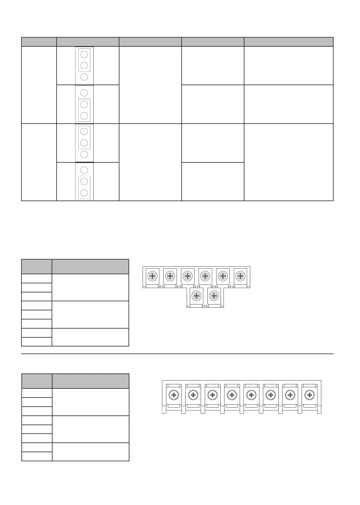
3.9 Power Terminals
Circuit protection must be installed before AC drive. See
section 2.3 of the user manual for the appropriate circuit
breaker for your drive.
Depending on the AC drive model, terminal labels and layouts
may be slightly different. Please see table and diagrams
below for details on terminal labels and their functions.
BR
L1(L)
L2 L3(N )
T1 T2
T3
P
Frame 1 - Three Phase
Models:
• TD400-20P5-13PH
• TD400-2001-13PH
• TD400-4001-3PH
• TD400-4002-3PH
AC Drive
Terminal
Terminal function
description
L1(L)
Main power inputL2
L3(N)
T1
AC Drive output, connect to
U/V/W terminals of motor
T2
T3
P
Externally connected
braking resistor
BR
L1(L) L2 L3(N) P BR T1 T2 T3
Frame 2 - Three Phase
Models:
• TD400-2002-13PH
• TD400-2003-13PH
• TD400-2005-3PH
• TD400-4003-3PH
• TD400-4005-3PH
Terminal
symbol
Terminal function
description
L1(L)
Main power inputL2
L3(N)
T1
AC Drive output, connect to
U/V/W terminals of motor
T2
T3
P
Externally connected
braking resistor
BR
 Loading...