EasyManuals Logo

Focusrite ISA One User Manual

Focusrite ISA One
2 pages
To Next Page IconTo Next Page
Page #1 background imageLoading...
Page #1 background image
ISA One & 430 MKII
Digital Option Installation
Digital Output Kit
The kit should contain:
Qty Description
1 AnaloguetoDigitalconvertercard
4 Crossheadscrews
Toolsrequired:-
No.1crossheadscrewdriver,Poziheadpreferred.
WARNING!
THE MODULE SHOULD BE DISCONNECTED FROM THE AC POWER
BEFORE ATTEMPTING TO CARRY OUT THE FOLLOWING INSTRUCTIONS.
ALLOW THE MODULE TO COOL BEFORE STARTING INSTALLATION OF
THE DIGITAL OPTION.
ANTI-STATIC PRECAUTIONS SHOULD BE TAKEN WHEN HANDLING THE
CARD OUTSIDE OF ITS ANTI-STATIC BAG: ONLY HANDLE THE CARD BY
GRIPPING ITS EDGES AND AVOID TOUCHING ANY OF THE COMPONENT
PARTS OTHER THAN THE CABLE AND CONNECTORS. PLACE THE UNIT
ON A FLAT, CLEAN SURFACE.
ISA 430 MKII Instructions
Removing the Top Cover
Removethe11crossheadscrewsxingthetopcovertothetopandsides
oftheISA430MKIIunit.
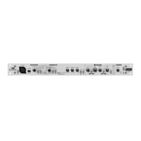
Removing the Digital Option Cover on the Rear Panel
Therearpaneldigitalconnectorareaisaccessedbyremovingtherear
coverplateabovethe‘DIGITALOUTPUT’labelling.Theplateisremovedby
removingthetwocrossheadscrewsshownbelow.Retainthesescrewsfor
securingthedigitalcardinplacelater.
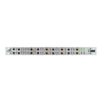
Installing the Digital Option
Thedigitalcardismountedinplaceusingthefoursuppliedcrosshead
screwsandthetwosupportbracketswithintheunit,asshownbelow.
Fitting the Card
PlacethecardintotheunitwiththecablepointingtowardssocketJ42.
Restthecardonthebracketssothatthefourholesonthecardlineup
withthefourholesonthebracket.Screwthecardintoplaceusingthe
fourcrossheadscrewsandthetwoscrewsretainedfromthereardigital
optioncover.
Oncethecardhasbeensecuredintoplace,thedigitalcardribboncable
canbeconnectedtothesocketontheISA430MKIIlabelledJ42.The
connectorshouldbepressedrmlydowninplacetoensureagood
contact.
N.B.Thecablehasanorientationtabthatshouldalignwiththe
orientationnotchinthesocket.Ifthisisnotcorrectlyaligned,thecable
willnottcorrectly–do not force it!
Replacing the Top Cover
Thetopcovershouldnowbereplaced,usingthe11crossheadscrewsto
securermlytothechassis.
Theinstallationisnowcompleteandtheunitcanbereconnectedtothe
ACpower.
Initialising the ISA 430 MKII Unit with the ADC tted
TheISA430MKIIrecognisestheinstallationofthedigitalcardafteryou
havecarriedoutthefollowingstep:
•PressandholddownanyswitchonthefrontofISA430MKIIwhilst
poweringuptheunit.Oncethefrontpanelisilluminated,releasethe
switch.
Thedigitalcardwillnowbeactive.Thisisaone-timeaction.Once
initialised,theISA430MKIIwillrecognisethepresenceoftheADCeach
timetheunitispoweredup.
PleaserefertothefullUserGuidefordigitalcardoperation.
DIGITAL OUTPUT
REMOVE THESE TWO SCREWS
REAR PANEL
REAR PANEL
SIDE VIEW
TOP VIEW
TOP VIEW
REAR PANEL
J42
ORIENTATION
NOTCH
SUPPORT BRACKETS FOR ADC CARD
4x SCREW HOLES FOR MOUNTING
ADC USING 4x CROSSHEAD
SCREWS SUPPLIED IN KIT
SOCKET FOR
ADC CABLE
REAR PANEL
ADC CARD
ATTACH CARD TO BRACKETS
USING 4x CROSSHEAD SCREWS
SUPPLIED IN KIT
REPLACE SCREWS REMOVED
FROM REAR OPTION COVER

Questions and Answers:

Question and Answer IconNeed help?

Do you have a question about the Focusrite ISA One and is the answer not in the manual?

Focusrite ISA One Specifications

General IconGeneral
TypeMicrophone Preamp
Phantom Power+48V
Number of Channels1
EQNo
Maximum Output Level+22 dBu
Inputs1 x XLR, 1 x 1/4"
Output1 x XLR (Balanced), 1 x 1/4" (Unbalanced)
ImpedanceLine Input: 10kΩ
Analog Inputs1 x XLR, 1 x 1/4"
Analog Outputs1 x XLR, 1 x 1/4"
Other I/O1 x 1/4" (Insert)
THD+N< 0.001%
Optional Digital CardYes
Power SupplyInternal

Related product manuals