ISA One Instructions
Removing the Top Cover
Removethe10crossheadscrewsxingthetopcovertothetopandsides
oftheISAOneunit.
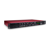
Removing the Digital Option Cover on the Rear Panel
Therearpaneldigitalconnectorareaisaccessedbyremovingtherear
coverplateabovethe‘DIGITALOUTPUT’labelling.Theplateisremovedby
removingthethreecrossheadscrewsshownbelow.Retainthesescrews
forsecuringthedigitalcardinplacelater.
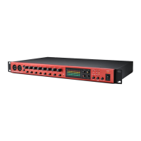
Installing the Digital Option
Thedigitalcardismountedinplaceusingthreeofthefoursupplied
crossheadscrewsandthethreesupportledgeswithintheunit,as
shownbelow.
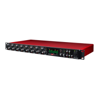
Fitting the Card
PlacethecardintotheunitwiththecablepointingtowardssocketJ14A.
Restthecardontheledgessothatthethreeholesonthecardlineup
withthethreeholesonthesupportledges.Screwthecardintoplace
usingthreeofthefourcrossheadscrewsandthethreescrewsretained
fromthereardigitaloptioncover.
Oncethecardhasbeensecuredintoplace,thedigitalcardribbon
cablecanbeconnectedtothesocketontheISAOnelabelledJ14A.The
connectorshouldbepressedrmlydowninplace,untilthetwolatches
havelocked,toensureagoodcontact.
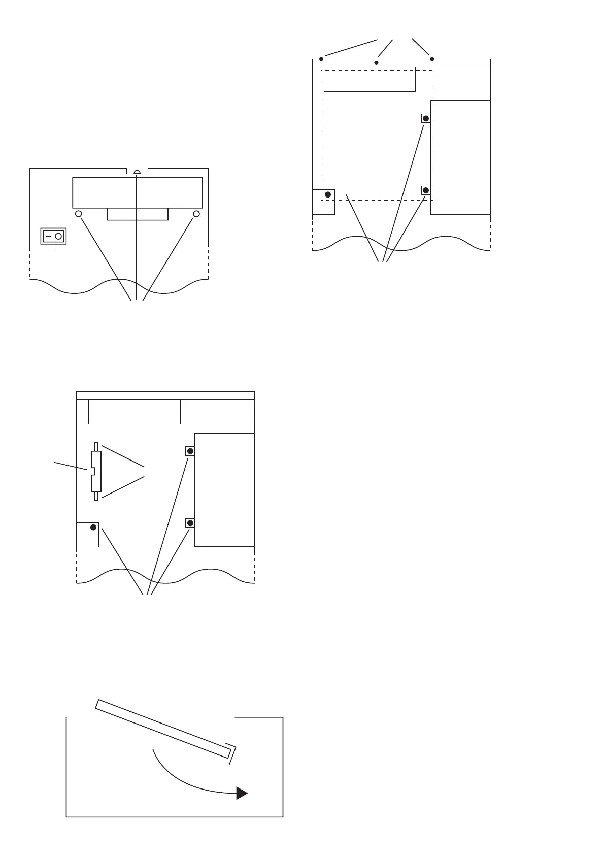
N.B.Thecablehasanorientationtabthatshouldalignwiththe
orientationnotchinthesocket.Ifthisisnotcorrectlyaligned,thecable
willnottcorrectly–
do not force it!
Replacing the Top Cover
Thetopcovershouldnowbereplaced,usingthe10crossheadscrewsto
securermlytothechassis.
Theinstallationisnowcompleteandtheunitcanbereconnectedtothe
ACpower.
Initialising the ISA One Unit with the ADC tted
TheISAOnerecognisestheinstallationofthedigitalcardafteryouhave
carriedoutthefollowingstep:
•PressandholddownanyswitchonthefrontofISAOnewhilstpowering
uptheunit.Oncethefrontpanelisilluminated,releasetheswitch.
Thedigitalcardwillnowbeactive.Thisisaone-timeaction.Once
initialised,theISAOnewillrecognisethepresenceoftheADCeachtime
theunitispoweredup.
PleaserefertothefullUserGuidefordigitalcardoperation.
Notes
Whensyncingtoanexternalclock,thesamplingfrequencyshouldbethe
sameonalldevicesinthedigitalchain.Ifyouexperienceanydifculties
installingthedigitaloption,pleasecontactFocusritetechnicalsupportat
supportteam@focusrite.com
FA0196-02