EasyManua.ls Logo

Focusrite TrakMaster Pro User Manual

Focusrite TrakMaster Pro
14 pages
To Next Page IconTo Next Page
Page #1 background imageLoading...
Page #1 background image
1
CONTENTS
CONTENTS........................................................................................................... 1
IMPORTANT SAFETY INSTRUCTIONS........................................................... 1
INTRODUCTION................................................................................................. 2
REAR PANEL CONNECTIONS.......................................................................... 2
GETTING STARTED – A QUICK GUIDE .......................................................... 3
FACILITIES AND CONTROLS............................................................................ 3
MICROPHONE INPUT ........................................................................................ 3
1/4" TRS INPUT ................................................................................................... 4
PRE-AMP............................................................................................................... 4
HPF......................................................................................................................... 4
MID SCOOP EQ .................................................................................................... 5
COMPRESSOR...................................................................................................... 5
LATENCY-FREE MONITORING........................................................................ 6
DIGITAL................................................................................................................. 6
LEVEL .................................................................................................................... 7
ADC EXT IN.......................................................................................................... 7
OPTIONAL DIGITAL OUTPUT.......................................................................... 7
DIGITAL OUTPUT INSTALLATION GUIDE .................................................... 8
FREQUENTLY ASKED QUESTIONS ............................................................... 10
TROUBLESHOOTING....................................................................................... 11
CONTACTING US.............................................................................................. 11
SPECIFICATIONS................................................................................................ 12
FOCUSRITE DISTRIBUTORS........................................................................... 14
IMPORTANT SAFETY INSTRUCTIONS
Please read all of these instructions and save them for future reference. Follow all
warnings and instructions marked on the unit.
Do not obstruct air vents in the rear panel. Do not insert objects through any
apertures.
Do not use a damaged or frayed power cord.
Unplug the unit before cleaning. Clean with a damp cloth only. Do not spill liquid
on the unit.
Ensure adequate airflow around the unit to prevent overheating. We recommend
leaving a blank 1U panel above the unit to aid ventilation.
Unplug the unit and refer servicing to qualified service personnel under the
following conditions: If the power cord or plug is damaged; if liquid has entered
the unit; if the unit has been dropped or the case damaged; if the unit does not
operate normally or exhibits a distinct change in performance. Adjust only those
controls that are covered by the operating instructions.
Do not defeat the safety purpose of the polarised or grounding-type plug. A
polarised plug has two blades with one wider than the other. A grounding type
plug has two blades and a third grounding prong. The wider blade or the third
prong is provided for your safety. When the plug provided does not fit into your
outlet, consult an electrician for replacement of the obsolete outlet.
WARNING: THIS UNIT MUST BE EARTHED BY THE POWER CORD.
UNDER NO CIRCUMSTANCES SHOULD THE MAINS EARTH BE
DISCONNECTED FROM THE MAINS LEAD.
This unit is supplied with an external power supply dependant on the region in which
the TrakMaster Pro is purchased. To avoid the risk of fire, replace the mains fuse only
with the correct value fuse, as marked on the plug. The external power supply unit
contains no user serviceable parts. Refer all servicing to a qualified service engineer,
through the appropriate Focusrite dealer.
RACK VENTILATION: PLEASE ENSURE THE TRAKMASTER PRO IS
PLACED TOWARDS THE BOTTOM OF YOUR EQUIPMENT RACK,
WITH SUFFICIENT SPACE ABOVE AND BELOW FOR VENTILATION.
Question and Answer IconNeed help?

Do you have a question about the Focusrite TrakMaster Pro and is the answer not in the manual?

Focusrite TrakMaster Pro Specifications

General IconGeneral
Channels1
CompressorYes
Frequency Response20Hz-20kHz
InputsXLR, 1/4"
OutputsXLR, 1/4"
Gain Range60dB

Summary

IMPORTANT SAFETY INSTRUCTIONS

General Safety Precautions

Covers multiple safety points like vents, cords, cleaning, and airflow.

Earthing and Power Cord Warning

Specific warning about the unit's earthing requirement.

Power Supply Unit and Fuse

Information about the external power supply and fuse.

Rack Ventilation Recommendation

Advice on proper unit placement for airflow.

INTRODUCTION

TrakMaster Pro Overview and Design

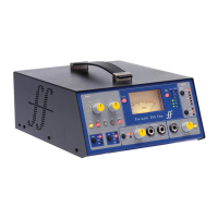
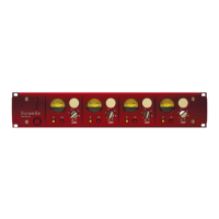
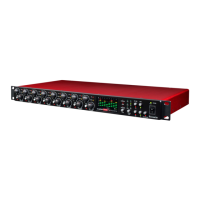
General description of the unit's purpose and core features.

REAR PANEL CONNECTIONS

Rear Panel I/O Details

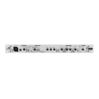
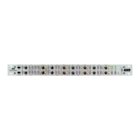
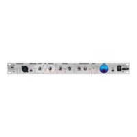
Details all rear panel connection types and their functions.

GETTING STARTED - A QUICK GUIDE

Initial Setup and Input Connection

Covers powering up, connecting sources, and setting initial levels.

Phantom Power and Gain Staging

Explains phantom power activation and proper input gain adjustment.

FACILITIES AND CONTROLS

Power Switch and Microphone Input

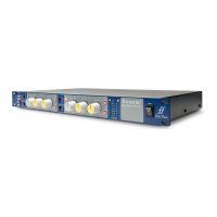
Details the power switch and the XLR microphone input with phantom power and impedance options.

1/4" TRS INPUT AND PRE-AMP

Line/Instrument Input and LEVEL Control

Explains the 1/4" TRS input, its switch, and the main LEVEL gain control.

HPF

High-Pass Filter Functionality

Describes the purpose and operation of the HPF switch.

MID SCOOP EQ

EQ Cut and Frequency Adjustment

Details the MID SCOOP EQ's cutting capabilities and frequency selection.

COMPRESSOR

Compressor Controls and Modes

Explains the IN switch, THRESHOLD, MAKEUP GAIN, and SQUASH modes.

COMP SLOW ATTACK AND MONITORING

Slow Attack Time and Latency-Free Monitoring

Covers COMP SLOW ATTACK and the LATENCY-FREE MONITORING system.

Headphone Mix, Level, and Mute Controls

Details the headphone monitoring controls.

DIGITAL SECTION

ADC LOCK LED Indicator

Explanation of the ADC LOCK status light.

LEVEL METERING AND ADC EXT IN

Front Panel Metering and Source Selection

Describes the dBFS meter and how to change the displayed signal.

External Mono Input Connection

Details the ADC EXT IN connector.

OPTIONAL DIGITAL OUTPUT

Digital Output Card and SPDIF

Information on the optional digital card, SPDIF output, and sample frequency.

EXT WORD CLOCK INPUT AND INSTALLATION

Word Clock Synchronization

Explains the BNC connector for external clock sync.

Digital Output Installation Guide

Covers kit contents, tools, and cover removal steps.

INSTALLING DIGITAL CARD

Digital Card Mounting Procedure

Step-by-step guide to install the digital card.

Jumper Removal and Use Settings

Instructions on jumper removal and setting for professional/consumer use.

WORD CLOCK IMPEDANCE AND TOP COVER

Impedance Settings for Word Clock

Details how to set word clock impedance.

Replacing the Top Cover

Instructions for reassembling the unit.

FREQUENTLY ASKED QUESTIONS

Signal Levels and Connections (+4dBu/-10dBV)

Explanation of signal level differences and connection types.

USER QUESTIONS AND TROUBLESHOOTING

Connectivity and Travel Questions

Addresses questions about balanced connectors, international travel, and retrofitting digital boards.

Troubleshooting Common Issues

Guides for resolving problems like no LEDs, no output, compressor/EQ issues, and ADC LOCK.

CONTACTING US

Support and Contact Information

Provides ways to get further help from Focusrite.

SPECIFICATIONS - INPUTS AND METERING

Mic, Line, and Instrument Input Specs

Detailed technical specifications for various inputs.

Level Meter and Hi Pass Filter Specs

Technical details for the meter and HPF.

SPECIFICATIONS - EQ, COMPRESSOR, AND ADC

Mid Scoop EQ and Compressor Parameters

Detailed specifications for the EQ and Compressor.

ADC Performance and Connectivity Specs

Technical data for ADC, word clock, and I/O connections.

FOCUSRITE DISTRIBUTORS

Global Distributor Contact Information

A list of international distributors and their contact details.

Related product manuals