7
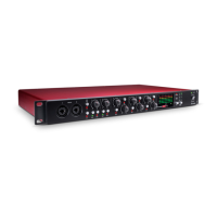
LEVEL
The meter on the front panel displays the level of the selected signal in dBFS, where
0dBFS (digital clipping point) relates to +22dBu of analogue signal level or 0dB of
compressor reduction (if viewing the COMPRESSOR). If the INPUT or OUTPUT
signals show over 0dBFS, they should be reduced using either the LEVEL knob in the
PREAMP section (for Input and Output without dynamics) or MAKEUP GAIN
knob in the COMPRESSOR section (for Output with dynamics). It is advisable to set
the incoming signal to be an average of around -10dBFS, peaking at around -6dBFS to
allow some headroom for occasional sudden loud bursts. To change the source signal fed
to the meter, simply use the switch as described below.
Pressing the switch beneath the INPUT, OUTPUT and COMP LEDs selects the
source signal that the meter on the front panel displays. Pressing the switch repeatedly
will cycle through the three options in sequence. If COMP is selected then the meter
displays the gain reduction of the compressor, where 0dB indicates that the processed
signal is unaffected.
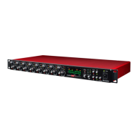
ADC EXT IN
This balanced (+4dBu) TRS jack connector on the rear panel allows an external mono
source, from another Focusrite channel strip for example, to be fed into the TM Pro for
digital conversion and subsequently monitoring purposes. The connected signal
becomes the right channel of the stereo signal (with the signal processed by the TM Pro
as the left channel) sent to the optional digital card for conversion. With nothing
connected to ADC EXT IN, the stereo signal sent to the ADC for digital conversion
will be the same mono internal signal processed by the TrakMaster Pro on both the L
and R channels. This stereo signal also becomes the ‘input’ signal in the LATENCY-
FREE MONITORING section. See the LATENCY-FREE MONITORING section
on page 6 for further details.
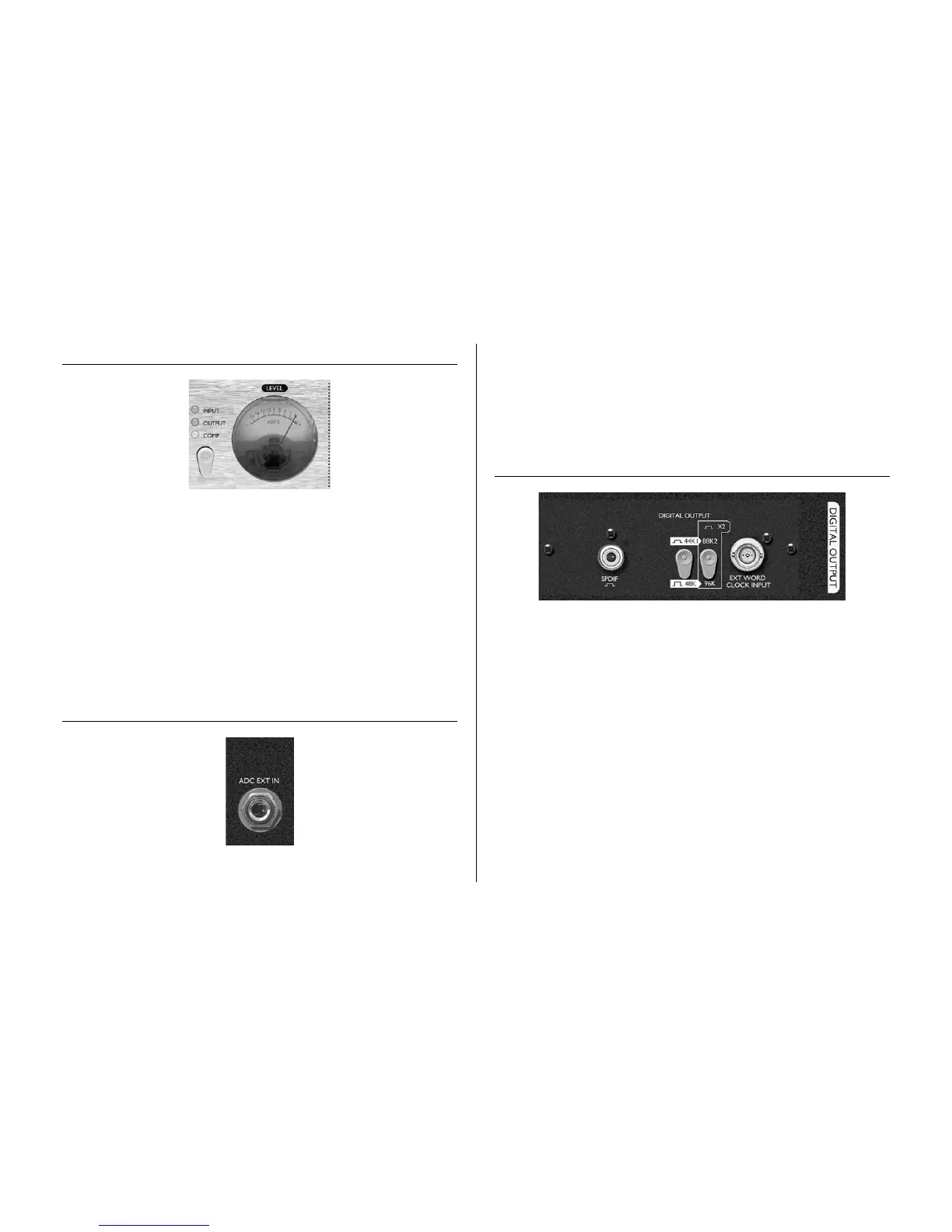
OPTIONAL DIGITAL OUTPUT
The TrakMaster Pro can be fitted with a digital output card. This allows quality digital
conversion of the recorded signal within the unit, plus an additional signal if making
use of the ADC EXT IN connector (see ADC EXT IN section for further details),
before transmitting directly to the DAW (interface or soundcard) or other recording
medium.
The optional digital converter card features one SPDIF output. Digital audio can be
transmitted at either 44.1, 48, 88.2 or 96kHz sample rates (selected using the switch(es)
on the rear panel) and with 24-bit resolution.
SPDIF OUTPUT
This connector transmits SPDIF format digital audio using an RCA phono connector.
If 16-bit resolution is required, the receiver should dither the incoming signal to
convert to 16-bit.
SAMPL E FREQUENCY
Two switches give a choice of four sample frequencies as marked on the rear panel. The
left hand switch selects between 44.1kHz (switch in) and 48kHz (switch out), and the
right hand switch doubles the selected frequency when switched in.