Page 5 of 10
ENG-0092.6
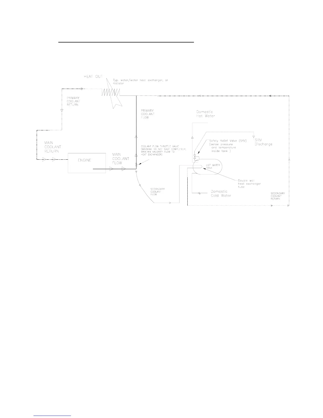
HEAT EXCHANGER INSTALLATION DIAGRAM
(Figure1)
4. A Temperature / Pressure relief valve (SRV) is factory installed. A drain hose
should be installed to comply with ABYC standards. (Section H-23 (23.7.4.2) in
the Installation of Potable Water Systems chapter.) Due to thermal expansion the
SRV may weep slightly. This is normal operation.
ELECTRICAL
1. Remove the AC wiring access cover by unscrewing the screw at the top of the
cover. The bottom is held in by a tab. The tab should be between the front case
and the insulation.
2. Connect the electrical supply by a qualified electrician. The electrical supply shall
be armored cable or conduit per NEC code ANSI/NFPA 70-1993. See figure 2 on
page 7 for Wiring Diagrams.
Note: Wiring diagram is located on the inside of the removable access
panel.