FORCE FLOW
FORCE FLOW
F
F
L
L
O
O
Q
Q
I
I
U
U
P
P
W.1.000
1150-D Burnett Ave, Concord, CA 94520 USA
1-800-893-6723 US & Canada, Fax: 925-686-6713
www.forceflow.com / info@forceflow.com
REF: T4\O&M\INDEX.\Y06.tcw etc (Y06.pdf etc)
SECTION
W.2.000
INDICATOR OPERATION
W.2.101
W.2.102
W.2.103
Keyboard Display Selections
Keyboard Menu - Quick Reference
Tank Load Mode
W.3.000
Code 9081 (Field Calibration)
Calibration of Slotted Platforms
Troubleshooting Tips
Parts List
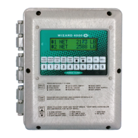
WIZARD Indicator with CARBOY-SCALE
INDEX
Code 9080 (Scale Set Up)
Code 9082-9083 (Feed Rate Format/Display Units)
Code 9084-9086 (Single or Dual Display/Tank Loading/Printer)
Code 9086 (cont...)-9089 (Time/Date/Calibration/Channels)
Code 4200 & 3256 (Set Point Configuration/4-20mA Output Configuration)
Code 3256 (cont...)
Indicator Wiring & Plumbing
Indicator Installation Instructions
Wizard Component Layout
INSTALLATION CHECK OFF LISTS
W.1.301
W.1.305
INDICATOR INSTALLATION
W.1.201
W.1.202-203
W.1.204
Installation Check-Off List
Installation Start-Up Check-Off List
SET-UP CODES - CUSTOM FORMATTING
W.2.201
W.2.202
W.2.203
W.2.204
W.2.205
W.2.206
MEMU OF DAY-TO-DAY OPERATIONS
W.2.104
W.2.105
W.2.106
W.2.107
W.2.108
MISCELLANEOUS
W.3.101
W.3.102
W.3.301
W.3.401
Low Level Alarm & Date Last Cleared
Clear Amount Used & Set Scale Zero
Set Scale Zero cont... & Allarm Reset
Review Daily Usage & Printing Report
Report (example) & Protocol
YOU
ARE
HERE !
INSTALLATION INSTRUCTIONS
W.1.101
W.1.101-4
W.1.102
W.1.103
W.1.104
W.1.105
W.1.106
W.1.108
Scale Drawing
1 to 4 Channel Configuration Drawing
Installation Drawing
Installation Introduction
Installation Instructions Steps 1 thru 4a
Installation Instructions Steps 4b thru 4f
Installation Instructions Steps 4g thru 5
Scale Operation
 Loading...